EA180 Servo Drive Manual
73
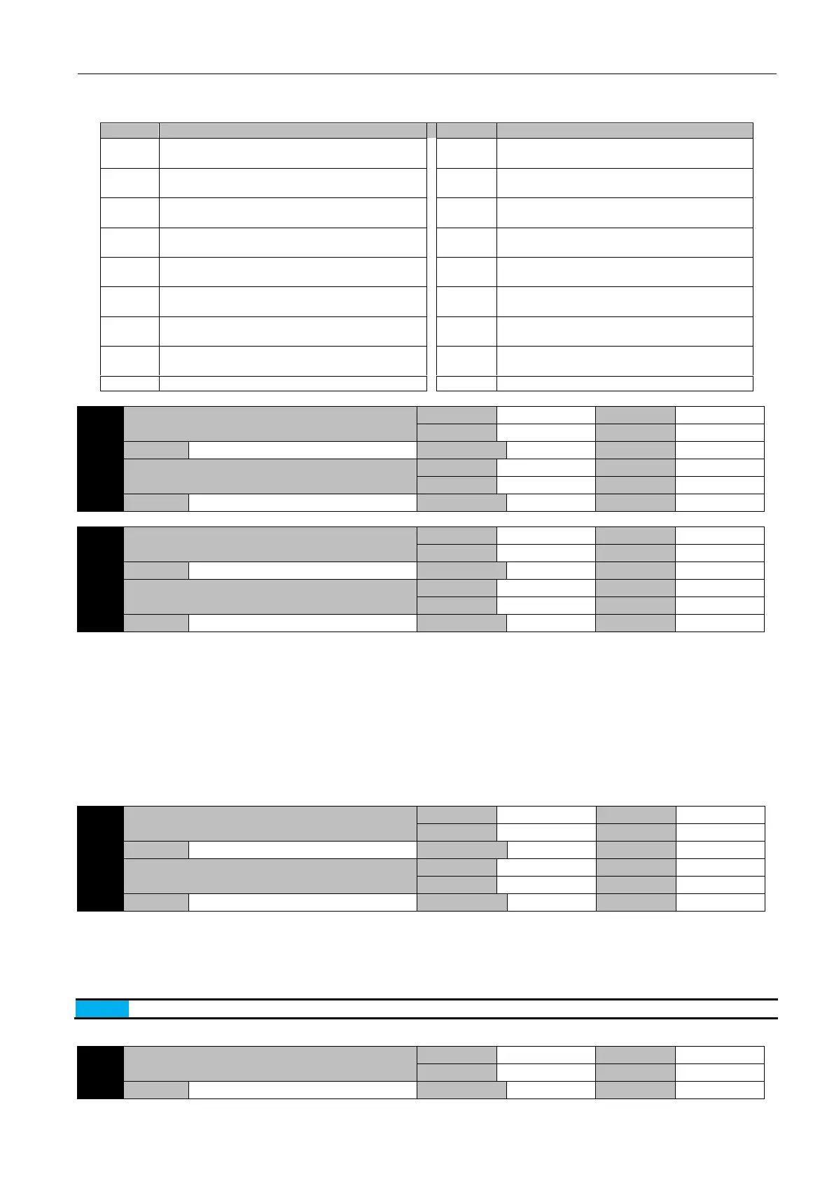
Parameter function: set the meaning of AO terminal output
When the output of the AO terminal is 10V, it means that the amount it represents reaches at the maximum value
The actual motor speed: 1V corresponds to
1000rpm
Write P6-42 direct output: -10000 ~10000mV
Speed command: 1V corresponds to 1000rpm
AI1 input: -10V ~ 10V corresponds to -10V ~
10V
Torque command: 1V corresponds to 100.0% of
rated torque
AI2 input: -10V ~ 10V corresponds to -10V ~
10V
Position deviation: 1mV corresponds to the
deviation of 1 command unit
Speed feedforward value: 1Vcorresponds to
1000rpm
Position deviation: 1mV corresponds to deviation
of 1 encoder unit
Torque feedforward value: 1Vcorresponds to
100.0% of rated torque
The speed corresponding to the pulse command:
1V corresponds to 1000rpm
Effective Gain: 0V first gain, 5V second gain
The actual torque output: 1V corresponds to
100.0% of rated torque
Position command transmission end: 5V
completed, 0V unfinished
Positioning completion: 5V completed, 0V
unfinished
Bus voltage: 1V corresponds to 100V
Write P6-41 direct output: -10000 ~10000mV
Parameter function: adjust the gain and bias of analog output terminals AO1 and AO2.
Analog output voltage = selected output * analog gain + analog bias. Note that these are signed numbers, so consider the operational
relation.
For example, "P6-35=0" and "AO1" represent motor speed:
The P6-37 gain is set to 1.00, and the P6-39 bias is set to 0, then the analog output is 3V, corresponding to the forward 3000rpm, and
the -3V corresponds to the reverse 3000rpm.
The P6-37 gain is set to 2.00, and the P6-39 bias is set to -5000, then the analog output 0V corresponds to the forward 2500rpm, the
-5V corresponds to the 0 speed, and the -10V corresponds to the reverse 2500rpm.
The P6-37 gain is set to 3.33, and the P6-39 bias is set to 5000, then the analog output is 0V, corresponding to the reverse 1500rpm,
the 5V corresponds to the 0 speed, and the 10V corresponds to the forward 1500rpm.
Parameter function: the desired voltage value that you want the AO terminal to output.
When P6-35, P6-36 set to 8 or 9, written by communication or keyboard input, P6-41 (corresponding to 8), P6-42 (corresponding to
9), the corresponding AO terminal output the corresponding voltage to test if the drive output, circuit and upper computer are in good
order.
For example: P6-35 is set to 8, and P6-41 is set to 5000 by keyboard or by communication. Then the AO1 terminal should output
5V.
When the servo power is restarted, the contents of the two parameters will be automatically cleared.
6.11 P7-xx Communication parameters
Modbus Communication address setting
 Loading...
