MN.00356.E - 003 147
Section 9.
LISTS AND SERVICES
22 LIST OF FIGURES
Fig.1 - Components electrostatic charge sensitive indication................................................ 10
Fig.2 - Elasticized band .................................................................................................. 10
Fig.3 - Coiled cord ......................................................................................................... 10
Fig.4 - WEEE symbol - 2002/96/CE EN50419 .................................................................... 11
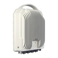
Fig.5 - ALFOplus2.......................................................................................................... 15
Fig.6 - ALFOplus2 connector side..................................................................................... 16
Fig.7 - Composition of ALFOplus2 and interface modules .................................................... 17
Fig.8 - Interface modules and carrier scheme.................................................................... 20
Fig.9 - Configuration with an external hybrid and a SP antenna, integrated or not.................. 20
Fig.10 - Configuration with 2 external hybrids and a not integrated DP antenna..................... 21
Fig.11 - Configuration with a not integrated DP antenna ..................................................... 22
Fig.12 - QoS example .................................................................................................... 26
Fig.13 .......................................................................................................................... 28
Fig.14 - ALFOplus2 blocks diagram .................................................................................. 31
Fig.15 - Available loops .................................................................................................. 35
Fig.16 .......................................................................................................................... 37
Fig.17 - Grounding connection ........................................................................................ 41
Fig.18 – Antenna adapter module (left: external side - right: internal side) ........................... 44
Fig.19 – ODU cavity....................................................................................................... 44
Fig.20 – ALFOplus with Standard mounting flange ............................................................. 45
Fig.21 – Installation of single flange ALFOplus2 over the antenna ........................................ 46
Fig.22 – ALFOplus with Standard mounting flange ............................................................. 47
Fig.23 – Installation of OMT flange ALFOplus2 over the antenna .......................................... 48
Fig.24 – Pole mounting of dual flanges ALFOplus2.............................................................. 49