82 MN.00356.E - 003
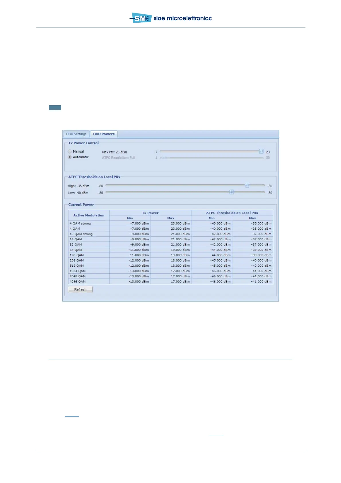
• in Tx Power Control select Automatic, ATPC is active
• in Ptx slide set the value in dBm for the Max Tx power (30 dB range)
• in ATPC Regulation set the dynamics of ATPC (from 30dB to 1dB), if max Regulation is required,
flag the ATPC Full Range (up to 30dB of attenuation)
• in ATPC Thresholds on Local PRx set the two thresholds to define the desired Rx power obtained
through remote side Tx power regulation (min.gap=3dB, advised=5dB)
• click Apply and Confirm.
Note: the difference between low ATPC threshold and upper modulation downshift threshold must be bigger
than 10dB.
There is no alarm if Rx Power is out from the range defined by ATPC thresholds.
Fig.53 - ATPC setting
11.9 OPTIMIZING ANTENNA ALIGNMENT WITH RX MEASUREMENT
When the whole radio link is on, antenna alignment can be optimised. Antenna alignment optimization is
performed depending on the Rx signal power at local and remote equipment and evaluating both local and
remote S/N value maximizing them. There are two possibilities to see the Rx signal power level:
• through WebLCT interface (by means of MNGT or other unabled port)
• relevant branch 1(A) through a voltmeter connected to MNGT port on the ODU (F03616 cable - see
Fig.29
).
In order to get the Rx signal power level via software, connect the PC to ALFOplus2 and start the WebLCT.
Into WebLCT is shown in the top status bar (Rx1A= -value dBm) see Fig.44
: