MN.00356.E - 003 83
If you’re using a voltmeter the Rx signal power level is available on the MNGT port of ODU, the measure-
ment can be performed with a proper cable (see Fig.29
). Following this last procedure, the voltage you’re
reading with the voltmeter is proportional to Rx power level, refer to Tab.15
.
Tab.15 - Voltage measured in 48V port
Typical Rx signal power level -40 dBm.
It is the most important item to optimise the antenna alignment, but in a situation of interference Rx level
can be good, BER acceptable but S/N margin low. This means that when Rx fields will decrease then BER
will increase fast. The situation can be easily shown with WebLCT software looking at Signal Quality level.
Into WebLCT Software select:
• Equipment menu
• Maintenance
• S/N Meas. card (see Fig.54
)
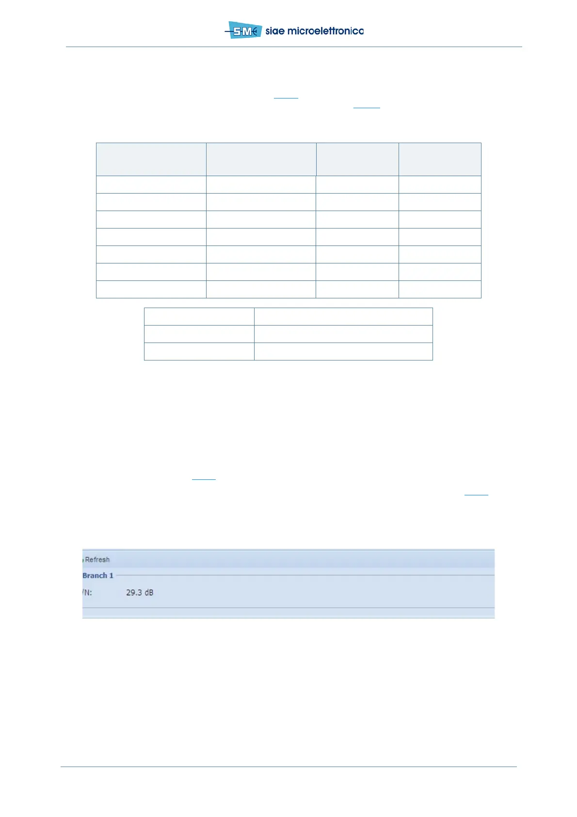
The best antenna alignment gives the higher Rx signal power level with the higher S/N ratio (see Fig.54
).
Fig.54 - S/N measurement monitoring
Received Signal [dBm] Signal Output [V] Error [dB] @25°C
Error [dB] @
-33°C ÷ +65°C
-20 3 ±2 ±4
-30 2.5 ±2 ±4
-40 2 ±2 ±4
-50 1.5 ±2 ±4
-60 1 ±2 ±4
-70 0.5 ±2 ±4
-80 0 ±2 ±4
Formula RSSI=Offset + (Signal Output)/Slope
Slope (V/dB) 0.05
Offset (dBm) -80