48 MN.00356.E - 003
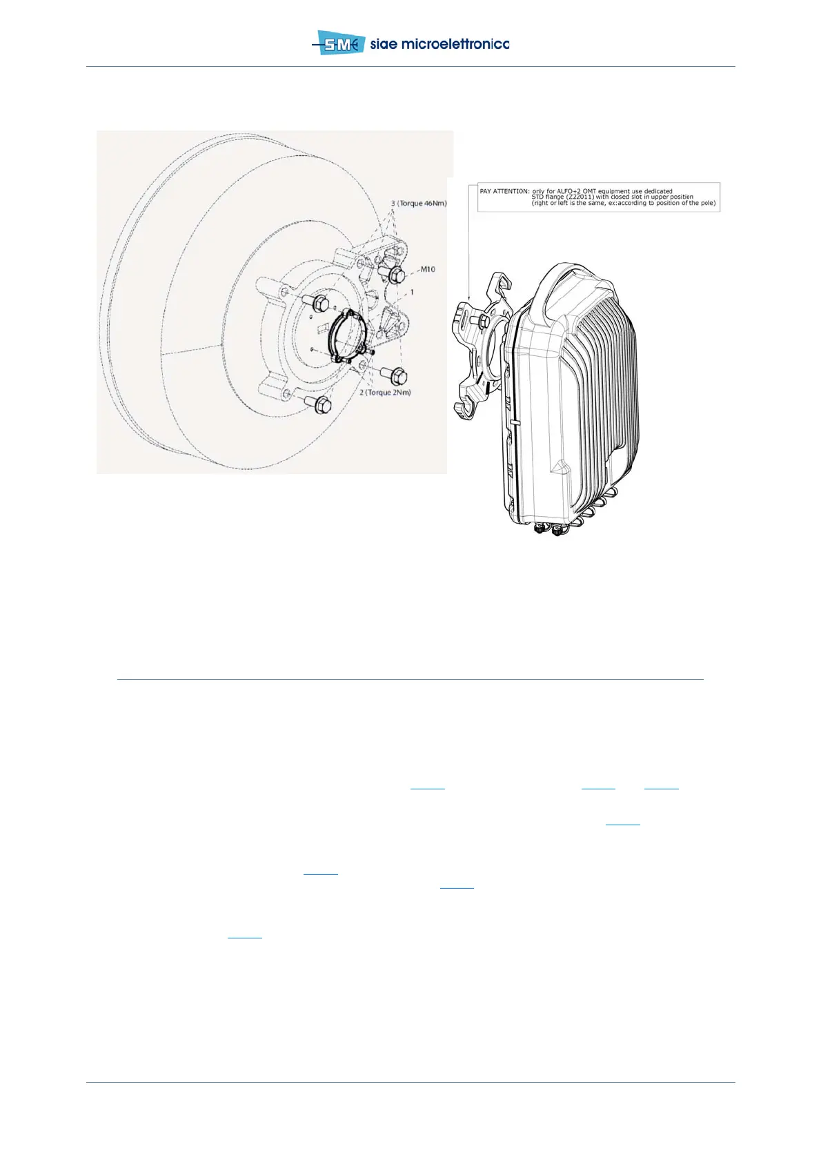
Fig.23 – Installation of OMT flange ALFOplus2 over the antenna
7.11 ODU INSTALLATION – DUAL OUTPUT FLANGE
The material is in kit V60519
• install the antisliding strip 1 and the plastic blocks 2 onto the pole
• hang the tooth of the supporting plate 3 onto the plastic blocks: two possibilities depending if the
rectangular opening must be on the left (see Fig.24
) or on the right (see in Fig.26 and Fig.27) re-
spect the pole.
• secure the plate to the pole with the two fixing bracket for 60–114 mm pole (see Fig.24
). Bolts and
nuts are available on the supporting plate kit. Use the four screws 5 and items 6, 7, 8, 9. Tightening
torque must be 32 Nm.
• install the ALFOplus2 (see Fig.25
) on the supporting plate using the six bolts M10 (shorter than the
four screws 5) through the six mounting holes (see Fig.26
). When all the bolts are positioned, tight-
en them (use 15mm spanner, torque=46mm)
• from the two RF flanges of ALFOplus2 two wave guides are necessary to connect them to the an-
tennas as in Fig.27
.