MN.00356.E - 003 41
7.5 GROUNDING CONNECTION
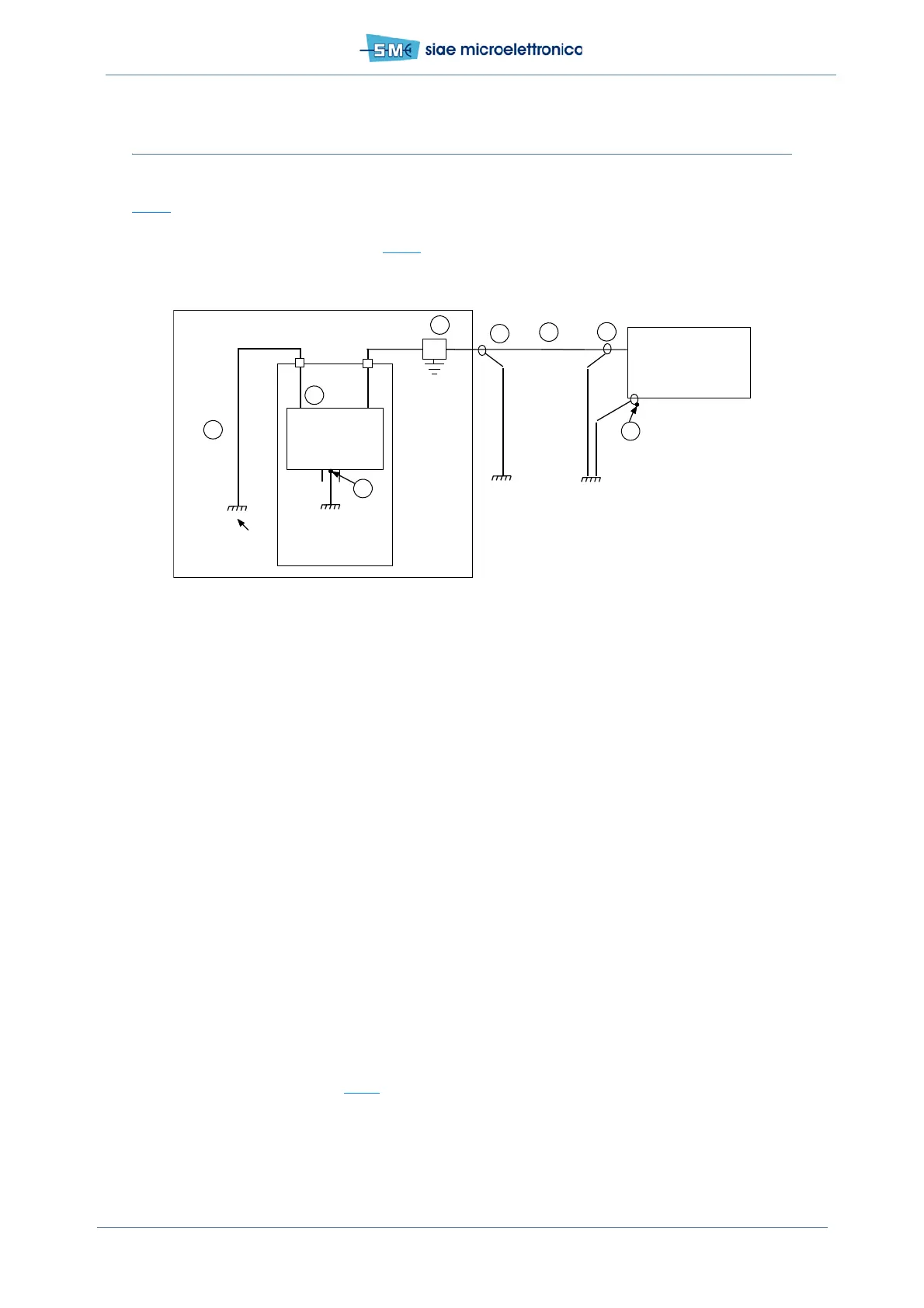
Fig.17 and annexed legend show how to perform the grounding connections.
The ODU must be connected to ground with the available grounding bolt M08303 and eyelet terminal
M06614, making reference to details of Fig.16
.
Legend
1. Ethernet Switch chassis grounding point. The cross section area of the cable used must be 4 sq.
mm.
2. ODU (ALFOplus2) grounding M6 bolt copper faston type. The cross section area of the cable used
must be 16 sq. mm
3. IDU–ODU interconnection cable (in example M02472 cat5)
4. Grounding cable kit type cable copper or copper alloy to connect the shield of interconnection cable.
5. Battery grounding point of IDU to be connected to earth by means of a cable with a section area
2.5 sq. mm. Length 10 m.
6. Grounding cords connected to a real earth internal of station. The cross section area of the cable
must be 16 sq. mm
7. Surge arrester (when needed).
Fig.17 - Grounding connection
7.5.1 Mounting instruction of grounding cable KIT ICD00072F (Univer-
sal, No tools)
The kit IDC00072F can be used for both IF cable and Ethernet cable.
Please, follow the procedure (see Tab.9
):
Ethernet
equipment
(IDU)
ODU
unit
2
5
(+)
(-)
4
Local
ground
rack
Chassis
ground
Indoor
Station
ground
6
1
4
3
7