80 MN.00356.E - 003
11.4 MODULATION & CAPACITY PARAMETERS
• Modulation profiles 4, 16, 32, 64, 128, 256, 512, 1024, 2048 and 4096QAM
4QAM and 16QAM have the strong version also; the modulation is the
same but the payload in the strong case is lower because of a bigger over-
head (stronger protection code).
• ACM Engine Enabled adaptive modulation (between Lower and Upper profiles):
• ACM Engine Disabled fixed modulation
• Reference modulation if ACM=Disabled, Ref. Modulation is the used modulation
if ACM=Enabled, Ref. Modulation limits the Tx power: output cannot
overtake the Ref Modul Tx Power (Max performance if Ref.Modulation
is 4QAM)
• Lower profile lower modulation profile used by ACM
• Higher profile higher modulation profile used by ACM
• ACM Table capacity of the link.
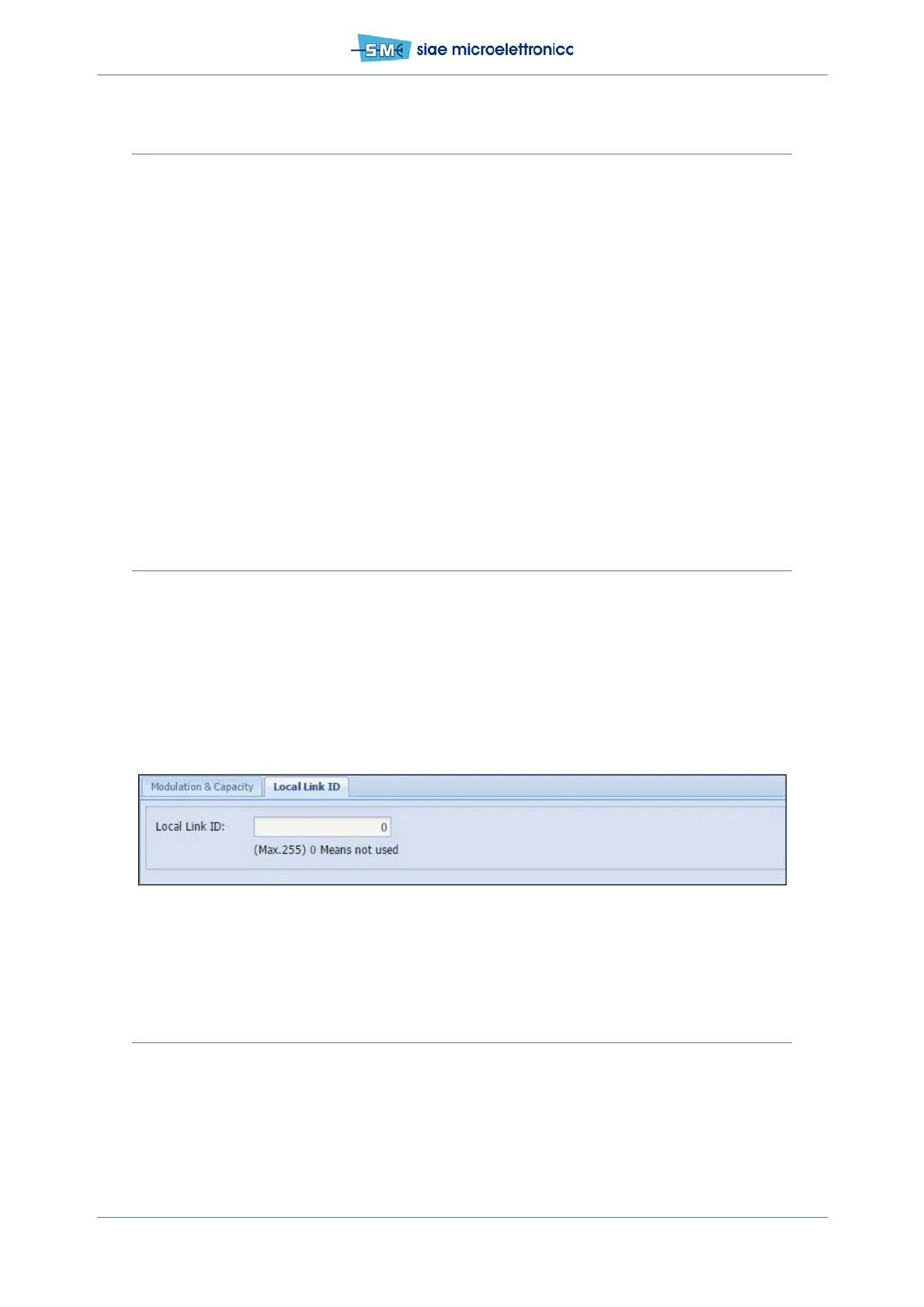
11.5 LINK ID
In WEBLCT select Equipment menu, BW & Mod./Link ID.
Select Local Link ID card:
• set the value used as Link ID between 1 and 255, 0=parameter not used and not checked
• click Apply and Confirm
• ...set the same Link ID value on remote unit. In case of Link ID mismatch (the unit receives a signal
with a Link ID different from the expected one) the alarm LinkID is active.
Fig.50 - Link ID setting
11.6 FREQUENCY SETTING
In WEBLCT select Radio menu, Radio Branch.
Select ODU Setting card:
• in Dplx Freq. menu select the desired value (Dplx freq. Is the Tx/Rx spacing) and push Apply and
Confirm
• in Tx Freq. menu select the desired Tx Freq. value in MHz (Local Tx Freq. = Rem Rx Freq.)