Paramount ME User’s Guide
102
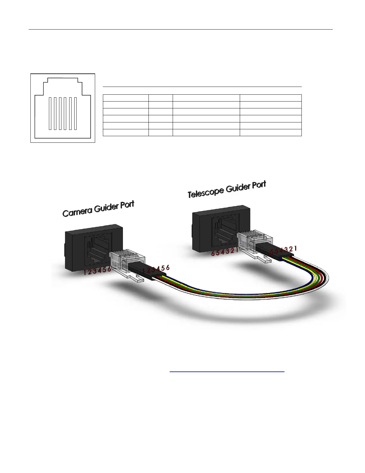
Figure 73: Pinout
diagram for the
camera guider port.
Guider Jack Wiring Specifications
The Adaptor Panel’s Guider port accepts a male RJ12 modular connector and provides
access to the directional switching used during autoguiding.
Pinouts for the Male RJ12 End of Guider Cable that Plugs into the
Camera Guider Port
Figure 74: Diagram showing the pinouts for the guider cable and the camera and guider ports.
*Note: The actual wire colors may differ.
P
†
PThis information may be used with SBIG ST-4, ST-5, ST-6 and SG-4 cameras.
See the section labeled “Guide Port” in the SG-4 Autoguider Operating Manual for SBIG
autoguider cable specifications.
Radio ShackP
®
P Cross Reference
The table below shows the Radio Shack® part number of several Adaptor Panel
components.