Paramount ME User’s Guide
58
Cable-Conduit
In addition to the built-in signal and power lines passed through the mount housing, the
Paramount ME is designed to provide ample space for additional cabling. Approximately
40 to 50 inches of cabling is required to snake through the mount and allow a small “loop”
of cabling inside the declination box. This loop is required so that the declination shaft
can rotate freely while the various cables move in tandem with the shaft.
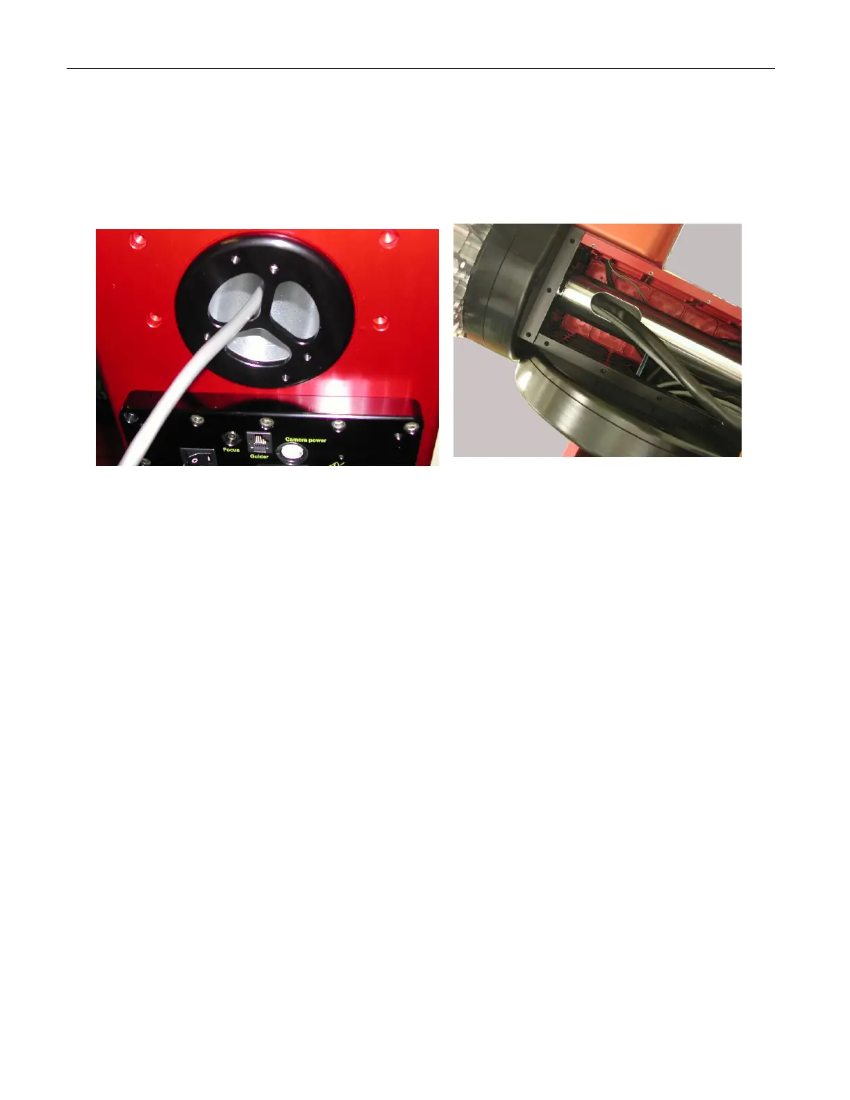
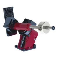
Figure 34: Route of “through the mount” cabling.
Additional cables enter the Paramount ME through the specially designed RA shaft nut on
the south end of the mount. From there, they exit the RA shaft inside the declination box
where some extra slack in the cable is required before passing the cable up through the
declination axis and out through the cable channel on the Versa-Plate.
Removing the RA and Dec Side Panels
The following procedure describes how to remove the Paramount ME's side right ascension
and declination side panels. This procedure is required when adding additional cabling.
Preserve the Mount's Elevation Setting
If the Paramount ME has been aligned to the celestial pole, make a pencil mark on
the Altitude Adjustment knob before raising the mount so that you can return the
mount to the same elevation (with less than one arcminute of error).
Note the approximate altitude (to the nearest degree) by using the altitude
elevation marks on the side of the wedge assembly. Next, make a mark between
the rotating Altitude Adjustment knob and the stationary cover on the bottom of
the altitude adjustment assembly.