Paramount ME User’s Guide
42
Balance the System
Attach your CCD camera and all other equipment (focuser, filter wheel, field rotator, dew
heater, etc.) to the optical tube assembly while balancing the mount. The telescope will
operate best when properly balanced. An unbalanced system can cause numerous
problems, such as stalling or “gear chattering” during slews. There is no clutching
mechanism on the Paramount ME. To achieve balance, disengage the worm from the gear
in each axis, and then adjust the position of the counterweights on the counterweight
shaft.
Always use extreme care when balancing the telescope! Make note
of the weight distribution on the telescope before disengaging the
worm block assembly from the gear. Always firmly grasp the OTA
or counterweight shaft before disengaging the worm and gear so
that you maintain control of the telescope.
The telescope could be damaged, or you could be seriously injured whenever the worm
gear is disengaged from the main gear on an unbalanced system.
The Paramount ME comes with two 9 kg (20 lb.) counterweights to balance the optical tube
assembly. To balance the right ascension axis, slide the counterweights up or down the
counterweight shaft until the system has no tendency to rotate in either direction.
If you use multiple detectors, such as a video camera to map, and a CCD camera to image,
the difference in weight might be enough to cause slewing problems when the detectors are
swapped. In this situation, you can quickly rebalance a system without disengaging the
worm and gear by marking various positions of counterweights on the shaft for different
configurations. It is very important not to change the system after telescope mapping has
been completed and a pointing model using TPoint has been created.
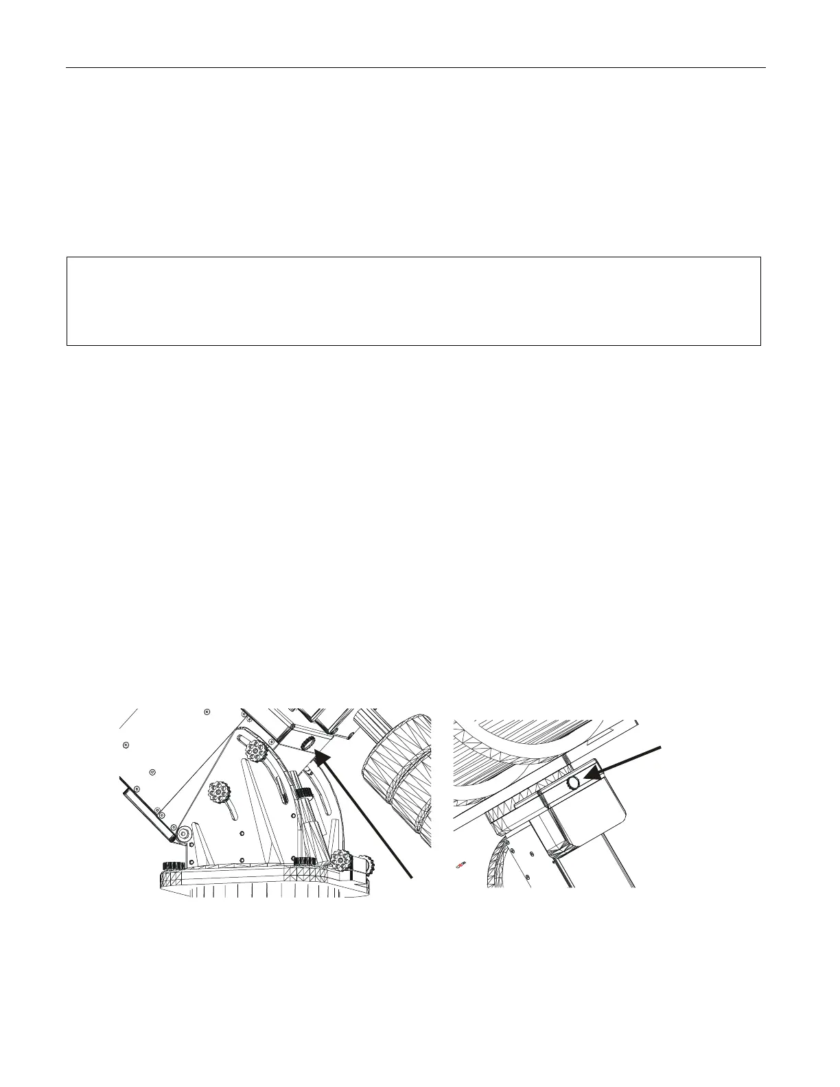
The worm blocks on the Paramount ME can permanently disengage the worm from the
gear while balancing the system. Though it is always a good idea to have a second person
available to help hold the OTA during balancing, this mechanism allows a single person to
achieve balance.
Figure 22: Location of the RA Balance Knob.
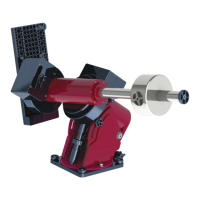
Figure 23: Location of the Declination
Balance Knob.