Paramount ME User’s Guide
31
Attach the Versa-Plate to the top of the declination housing using eight 1-inch ¼-20 socket
head cap screws (page X15X).
There are two cables that protrude from the top of the declination housing. Both must be
directed through the Versa-Plate cable channel. Make sure that you have just enough
cable protruding out of the top of the declination housing to reach the Instrument Panel.
Extra cable makes assembling the Instrument Panel box difficult. Too little slack and the
cables cannot be plugged into the slots on the Instrument Panel’s control board.
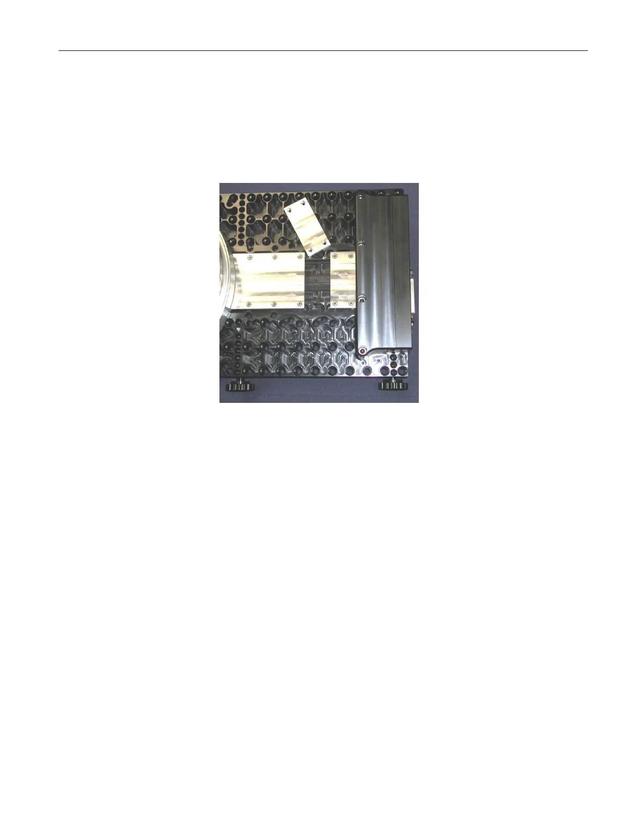
Figure 13: Channel Covers (unanodized for illustration purposes)
The channel covers are shown in XFigure 13X. There are three channel separate covers to
accommodate the three Versa-Plate mounting configurations. The “typical configuration”
uses the large cover and only one of the two rectangular covers. The “Schmidt-Cassegrain”
configuration uses only the large cover. The “Newtonian configuration,” shown above,
requires all three channel covers.
Plugging In the Instrument Panel Electronics
This section describes the procedure for properly plugging in the Instrument Panel
electronics, and is included for reference purposes only, since the Paramount ME is now
assembled and shipped with the Instrument Panel Housing and electronics already
mounted to the Versa-Plate.
After the cables are passed through the Versa-Plate cable channel, they must be plugged
into the appropriate slots on the Instrument Panel’s control board. Inspect the two cables
to identify the alignment notches (see XFigure 14X). Do not plug these cables in backwards!