Paramount ME User’s Guide
30
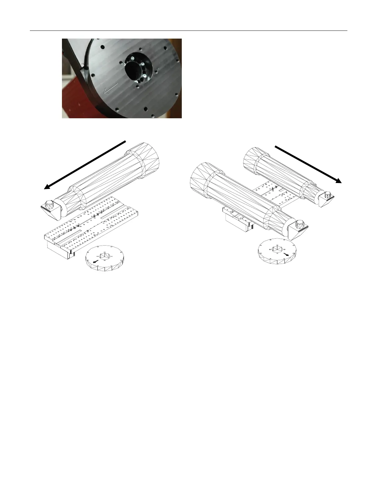
If you must remove the Versa-Plate for any
reason, please take note that an arrow is
machined into the declination hub as a
guide to ensure that the orientation of the
Versa-Plate is correct.
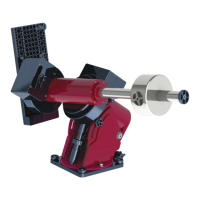
Specifically, attach the Versa-Plate so that
this arrow points in the same direction as
the light that comes into the optical tube
assembly (see XFigure 12X).
Figure 11: Photograph of the top of the declination housing (note machined arrow).
Figure 12: Typical (left) and wide (right) Versa-Plate mounting configurations. The black arrows
indicate the direction of incoming light. Note that the machined arrow on the declination hub points
in the same direction as the incoming light.
The Paramount ME is shipped with the Versa-Plate mounted in the “typical configuration”
as shown in the left drawing in XFigure 12X. Note that the arrow on the declination hub
points in the direction of incoming light to the telescope and toward the Instrument Panel
(mounted to the bottom of the Versa-Plate). This orientation ensures maximum rotation of
the declination axis without hitting the hard stop at -90 degrees declination.
The Versa-Plate can also be mounted at 90 degrees from the typical orientation, offering a
wide mounting surface that can accommodate multiple optical tube assemblies. Note the
machined arrow on the declination hub still points in the direction of the incoming light,
but not toward the Instrument Panel as in the typical configuration.
A third configuration (not pictured) places the Instrument Panel near the entrance pupil of
the telescope. In this orientation, cabling to the CCD camera follows the shortest route for
Newtonian telescopes. The Versa-Plate is rotated 180 degrees from the typical
configuration pictured above.
Note that the machined arrow must always point in the direction of incoming light,
regardless of the configuration.