NOTE
Images are for illustration purposes only. Refer to the label on the product to identify the plus and
minus input and output connectors.
Step 3: Connecting Power Optimizers in Strings
Youcanconstructparallelstringsofunequallength,thatis,thenumberofpoweroptimizersineach
stringdoesnothavetobethesame.Theminimumandmaximumstringlengthsarespecifiedinthe
poweroptimizerdatasheets.RefertotheSolarEdgeSiteDesignerforstringlengthverification.
NOTE
The total cable length of the string (including power optimizers’ cables) should not exceed
1000ft./300m from DC+ to DC- of the inverter. Use at least 11 AWG/ 4 mm² DC cables.
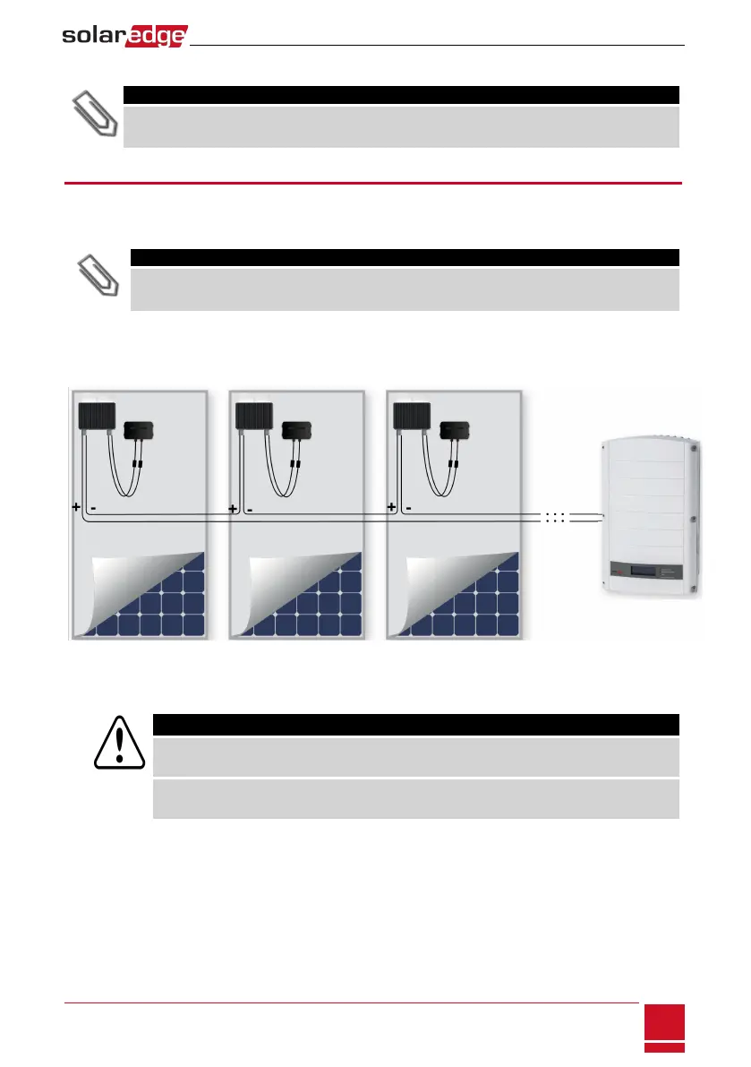
1. ConnecttheMinus(-)outputconnectorofthestring’sfirstpoweroptimizertothePlus(+)output
connectorofthestring’ssecondpoweroptimizer.
2.
Connecttherestofthepoweroptimizersinthestringinthesamemanner.
Figure 6: Power optimizers connected in series
3.
Ifyouintendtomonitortheinstallation,usingtheSolarEdgemonitoringportal,recordthephysical
locationofeachpoweroptimizer,asdescribedinProvidingInstallationInformationonpage61.
WARNING!
Input and output connectors are not watertight until mated. Open connectors should be mated to
each other or plugged with appropriate watertight caps.
Les connecteurs d’entrée et sortie ne sont pas étanches jusqu'à ce qu’ils soient accouplés. Les
connecteurs doivent être accouplés ou fermés avec des terminaux étanches.
Chapter 2: Installing the Power Optimizers
SolarEdge-StorEdge Installation Guide MAN-01-00262-1.0
15