Creating an Ethernet (LAN) Connection
ThiscommunicationoptionenablesusinganEthernetconnectiontoconnecttheinvertertothe
monitoringportalthroughaLAN.
Ethernetcablespecifications:
l Cabletype–CAT5/CAT6
l Maximumdistancebetweentheinverterandtherouter–100m/330ft.
NOTE
If using a cable longer than 10 m/33 ft in areas where there is a risk of induced voltage surges by
lightning, it is recommend to use external surge protection devices. For details refer to:
http://www.solaredge.us/files/pdfs/lightning_surge_protection.pdf. If grounded metal conduit are
used for routing the communication wires, there is no need for a lightning protection device.
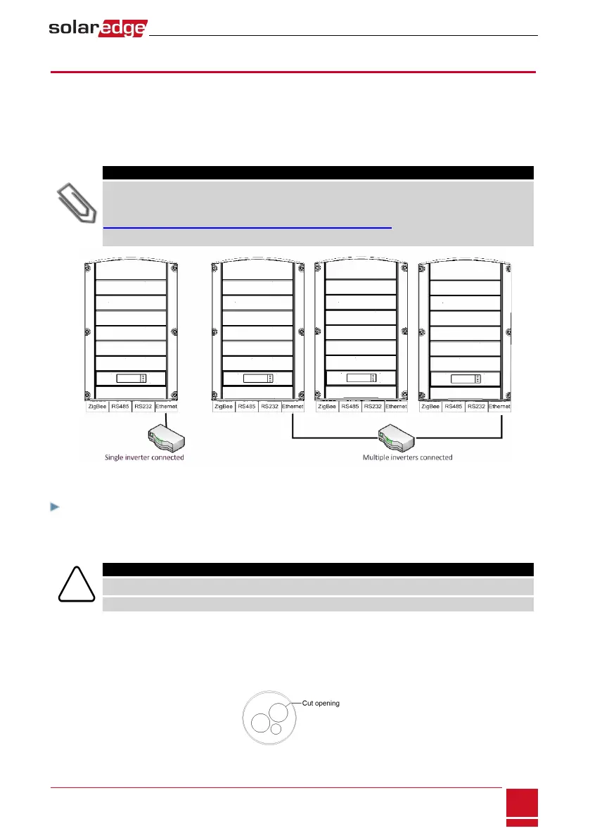
Figure 32: Example of Ethernet connection
To connect the Ethernet cable:
1. RemovetheinvertercoverasdescribedinRemovingtheInverterCoveronpage39.
2. Openthecommunicationgland#1.
CAUTION!
The gland includes a rubber waterproof fitting, which should be used to ensure proper sealing.
Le cote interne du gland contient une rondelle qui doit être utilisée pour une bonne étancheïté.
3. Removetheplasticsealfromthelargeopeningthathasacutintherubberfitting.
4. RemovetherubberfittingfromtheglandandinserttheCAT5/6cablethroughtheglandandthrough
theglandopeningintheinverter.
5. Pushthecableintothecutopeningoftherubberfitting.
Figure 33: Rubber fitting
Chapter 10: Setting Up Communication to the Monitoring Portal
SolarEdge-StorEdge Installation Guide MAN-01-00262-1.0
73