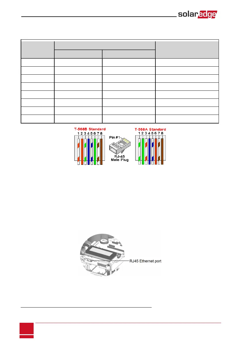
CAT5/6standardcableshaveeightwires(fourtwistedpairs),asshowninthediagrambelow.Wirecolors
maydifferfromonecabletoanother.Youcanuseeitherwiringstandard,aslongasbothsidesofthe
cablehavethesamepin-outandcolor-coding.
RJ45 Pin #
Wire Color
1
10Base-T Signal
100Base-TX Signal
T568B T568A
1 White/Orange White/Green Transmit+
2 Orange Green Transmit-
3 White/Green White/Orange Receive+
4 Blue Blue Reserved
5 White/Blue White/Blue Reserved
6 Green Orange Received-
7 White/Brown White/Brown Reserved
8 Brown Brown Reserved
Figure 34: Standard cable wiring
6. Useapre-crimpedcabletoconnectviagland#1totheRJ45plugontheinverter'scommunication
boardor,ifusingaspoolofcable,connectasfollows:
a. Insertthecablethroughgland#1.
b. Removethecable’sexternalinsulationusingacrimpingtoolorcablecutterandexposeeight
wires.
c. InserttheeightwiresintoanRJ45connector,asdescribedinFigure34
d. Useacrimpingtooltocrimptheconnector.
e. ConnecttheEthernetconnectortotheRJ45portonthecommunicationboard.
Figure 35: The RJ45 Ethernet connection
1
The inverter connection does not support RX/TX polarity change. Supporting crossover Ethernet cables depends on the
switch capabilities.
SolarEdge-StorEdge Installation Guide MAN-01-00262-1.0
74
Creating an Ethernet (LAN) Connection