AllLEDsturnonwhiletheinverterisbeingconfigured.
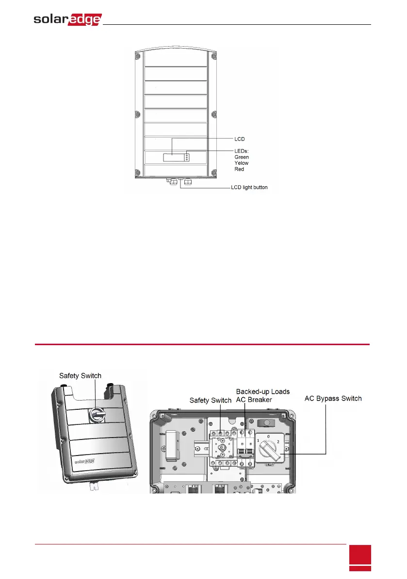
Figure 8: Inverter front view
l AC and DC conduit entries:ConnectionpointsoftheStorEdgeConnectionUnit.
l ON/OFF switch:TurningthisswitchONstartstheoperationofthepoweroptimizers,enablespower
productionandallowstheinvertertobeginexportingpowertotheutilitygrid/backed-uploads.
TurningitOFFreducesthepoweroptimizervoltagetoalowsafetyvoltageandinhibitsexportationof
power.WhenthisswitchisOFF,theinvertercontrolcircuitryremainspoweredup.
l LCD light button:PressingthisbuttonlightsuptheLCDfor30seconds.Inaddition,youcanpress
thisbuttontoaccessconfigurationmenuoptions,asdescribedConfiguringtheInverterUsingtheLCD
LightButtononpage43.
l Two communication glands,forconnectionofinvertercommunicationoptions.Eachglandhas
threeopenings.RefertoSettingUpCommunicationtotheMonitoringPortalonpage71formore
information.
StorEdge Connection Unit Interfaces
ThefollowingcomponentsarepartoftheStorEdgeConnectionUnitandmaybeaccessedfor
troubleshootingormaintenance.
Figure 9: StorEdge Connection Unit
Chapter 3: Installing the Inverter
SolarEdge-StorEdge Installation Guide MAN-01-00262-1.0
19