Chapter 1: Overview
StorEdge™isSolarEdge'sall-in-onesolutionthatusesasingleon-gridDCoptimizedinvertertomanage
andmonitorbothsolarpowergenerationandenergystorage.Homeownersareautomaticallyprovided
withbackuppowerintheeventofgridinterruptiontopowerpre-selectedloads.Solarenergycanbe
storedinabatteryforSmartEnergyManagementapplicationssuchasexportcontrol,offeringdemand
responseandpeakshaving,andperformingtimeofuseshiftingforreducedelectricbills.
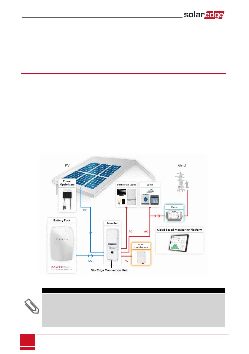
The StorEdge Solution Components
l The StorEdge Inverter with StorEdge Connection Unit -Theinvertermanagesbatteryandsystem
energy,inadditiontoitstraditionalfunctionalityasaDC-optimizedPVinverter.
TheStorEdgeConnectionUnit,locatedatthebottomoftheinverter,allowssimpleinstallationand
connectivitytoothersystemcomponentsandincludesaDCSafetySwitch.
l The SolarEdge Electricity Meter-Themeterisusedbytheinverterforexport/consumption
readings,andforSmartEnergyManagementapplications,suchas:exportlimitation,time-of-use
profileprogrammingandmaximizingself-consumption.
ThemeterisrequiredonlyinsystemsusingSmartEnergyManagementapplications(itisnotrequired
forStorEdgesystemsusedonlyforbackuppower).
l The Auto-transformer-Theauto-transformerhandlesthephaseloadbalancing.Itisrequiredonlyin
systemsprovidingbackuppower.
l The Battery-ADCcoupledbatterydesignedtoworkwiththeSolarEdgesystem.
Figure 1: StorEdge system components
NOTE
l Additional SolarEdge inverters (without batteries) can be connected with RS485. The inverters will
participate in export limitation and maximizing self-consumption (Maximizing self-consumption for
multiple inverters supported from Q2 2016).
Connecting multiple inverters with RS485 master-slave connection requires an RS485 Expansion
Kit (available from SolarEdge).
l PV modules connected to power optimizers are not mandatory for Time of Use (TOU) profile
programming and for backup power.
SolarEdge-StorEdge Installation Guide MAN-01-00262-1.0
8
Chapter 1: Overview