Warning # LCD text Comments and troubleshooting
1-4, 6-7 Fan X Failure Clean or replace the fan
5 Turn Switch Off to Configure
Appears when trying to access the Setup
menus during production
8 Connection Unit Low 9V Battery
Replace the 9V battery in the StorEdge
Connection Unit. Refer to 9V Battery
Replacement on page 91.
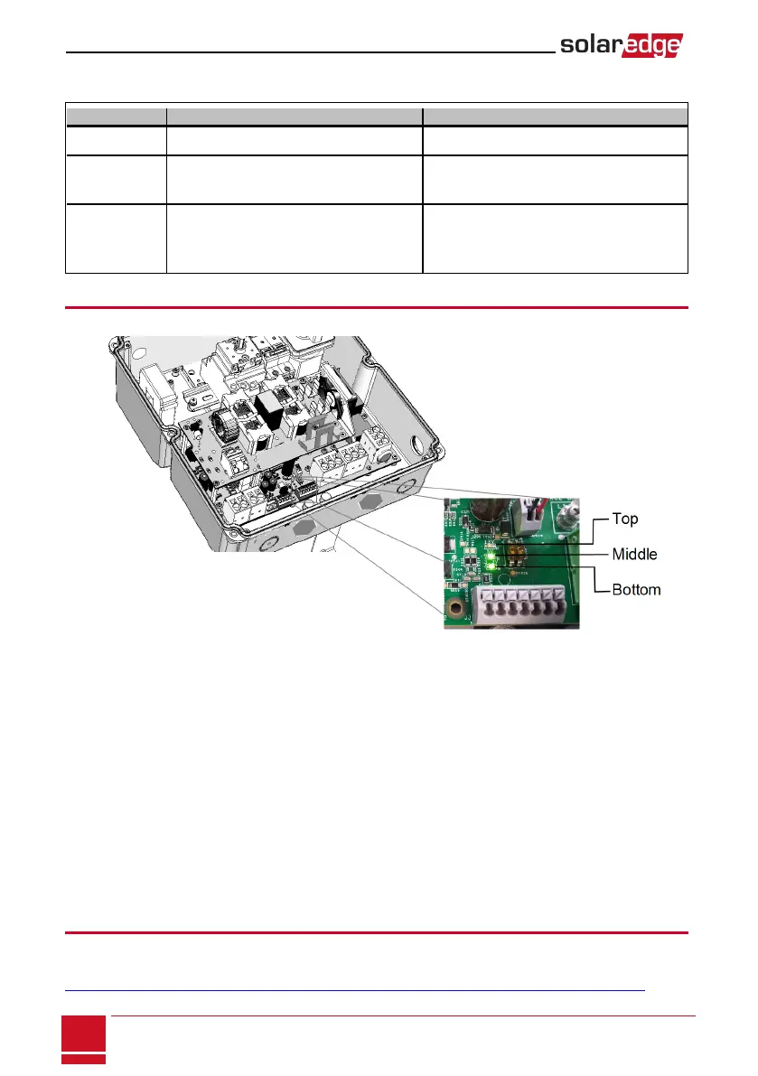
StorEdge Connection Unit LEDs
TherearethreeLEDsonthelowerboardoftheStorEdgeConnectionUnit,neartheDIPswitches:
l
l
l
Figure 41: StorEdge Connection Unit LEDs
In normal operation, themiddleandbottomLEDsindicateauxiliary voltages (13V from DC/DC, 5V
and 3.3V) andshouldalwaysbelit.
ThetopLEDshouldbelitwhentheinverterDCvoltage isatleast200Vdc (check when both inverter
ON/OFF switch and StorEdge Connection Unit switch are ON). Youcancheckthestatusscreenfor
theVdcvalue.
IfallLEDsareOFF:
o
CheckthatACvoltageexistsintheinverter
o
CheckthatthecommunicationcablebetweentheStorEdgeConnectionUnitandthedigital
boardisproperlyconnected.
l IfthetopLEDisON,andmiddleandbottomLEDsareoff-aninternalfailurehasoccurred.Contact
SolarEdgesupport.
Power Optimizer Troubleshooting
Iftheinverterstatusscreenindicatesthatnotallpoweroptimizersarepairedornotallarereporting(P_
OKxxx/yyy,andx<y),thoseoptimizerscanbeidentifiedthroughtheLCD.Referto
http://www.solaredge.com/files/pdfs/products/inverters/non-responding-power-optimizers.pdf
SolarEdge-StorEdge Installation Guide MAN-01-00262-1.0
88
StorEdge Connection Unit LEDs
The warning is a status screen. To view the warning description, press the LCD button.Thefollowingisa
listofsystemwarnings: