109
Electrical Connection
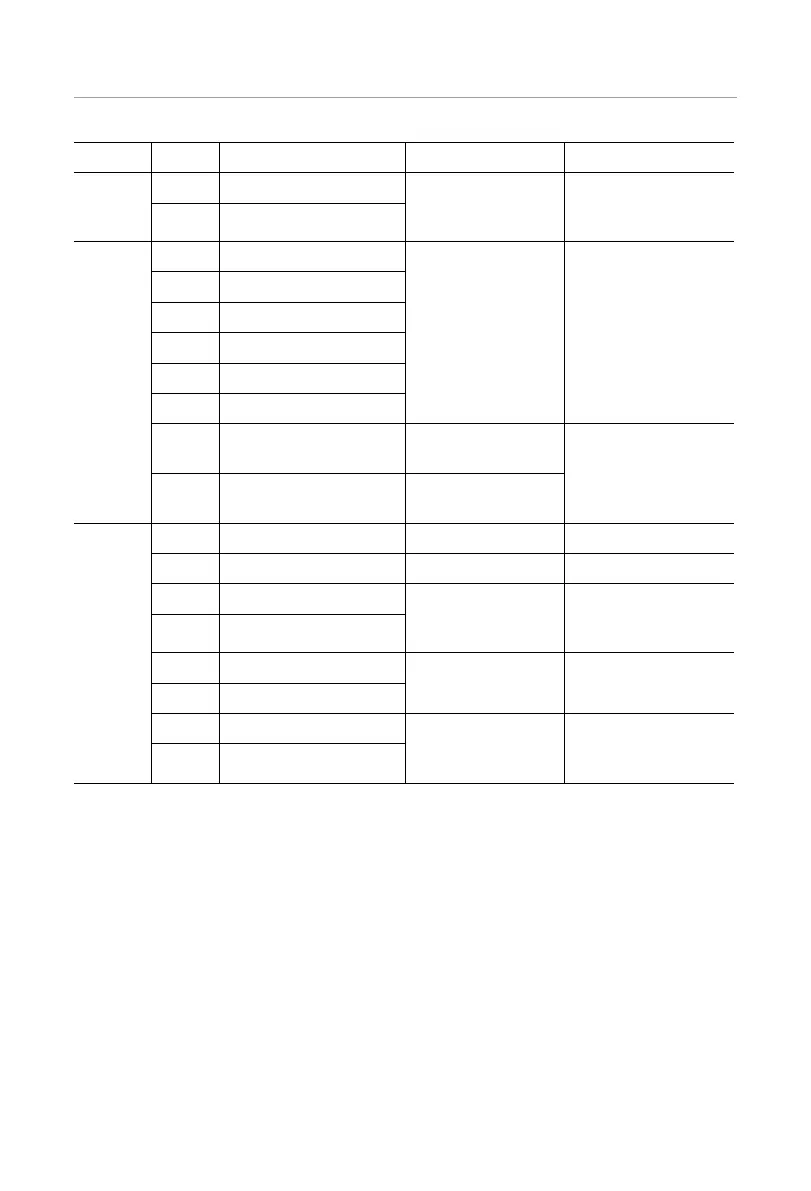
Icon PIN Definition Function Comment
P2
7
CAN_L
Parallel signal input
Parallel signal port
(RJ45)
8
CAN_H
P3
1 DRM1/5
Logic interface
signal
Logical interface is
for Australia (AS4777)
and other standards
2 DRM2/6
3 DRM3/7
4 DRM4/8
5 +3.3V_COM
6 COM/DRM0
7 remote 485A
RS485 differential
signal-A
communication with
SolaX's datahub,
EV-Charger and oth-
er internal devices
8 remote 485B
RS485 differential
signal-B
P4
9 12V_COM 12V Energy supply
10 GND GND Ground connection
11 modulbus 485A
Modulbus485
485 port for com-
munication with oth-
er external devices
12 modulbus 485B
13 DO_1
Output drycontact Output drycontact
14 DO_2
15 DI_1
Input drycontact Input drycontact
16 DI_2
* Professional personnel can use pins 11 and 12 to realize data acquisition and external
control functions. The communication protocol is Modbus RTU. For details, please contact
us.
* If customers want to use the inverter dry contact to control external equipment (such as
a heat pump), it can be used with our Adapter Box.
* Only DRM 0/1/5 are available, others are under development.
* The inverter can be shut down through DRM0.

 Loading...


