111
Electrical Connection
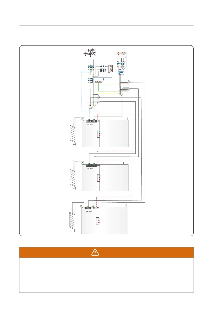
• Diagram 2: System diagram without SolaX X3-PBOX device
N
R
S
T
R
PE
N
S T R
N
S T
PE
R PE
N
S T R
N
S T PE
R PE
N
S T R
N
S T PE
Inverter
(master)
Breaker
T-BAT-SYS
CT
COM (P1)
PV1
PV2
Inverter
(slaver1)
Inverter
(slaver2)
BAT+BAT-BMS
Grid
EPS
COM
METRER/CT
Main
breaker
PE-BAR
RCD
Loads
N-BAR for
EPS loads
Grid
PV1
PV2
PV1
PV2
Grid
EPS
Grid EPS
COM
METRER/CT
COM
METRER/CT
BAT+BAT-BMS
BAT+BAT-BMS
T-BAT-SYS
T-BAT-SYS
COM (P1)
Breaker
N-BAR for loads
Loads
Figure 7-41 System diagram without SolaX X3-PBOX device
WARNING!
• Many cables are connected in these parallel systems, therefore it is strongly required
that cables must be connected according to correct line sequence (R-R, S-S, T-T,
N-N). Otherwise, any misoperation may cause the system running failed.
• In diagram 2, INCORRECT line sequence (R-R, S-S, T-T, N-N) will damage the inverter.
To avoid the damage, set the default Enable in External ATS interface under the
Advance Settings as Disable.
 Loading...


