EasyManuals Logo

SolaX Power X3-IES Series User Manual

SolaX Power X3-IES Series
228 pages
To Next Page IconTo Next Page
To Previous Page IconTo Previous Page
Page #78 background imageLoading...
Page #78 background image
70
Mechanical Installation
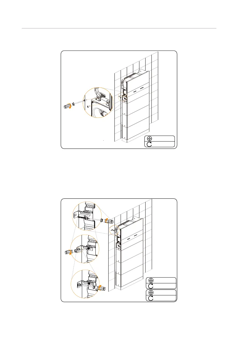
Step 16: Lock the screws on both sides of the inverter with the BMS.
M5 * 14
2±0.1 N·m
Figure 6-26 Locking the inverter with the BMS
Step 17: Lock the inverter brackets on both sides of the inverter.
1. Tighten but not lock the self-tapping screws into the wall.
2. Lock screws on the inverter.
3. Lock screws into the wall.
M5 * 10
2±0.1 N·m
ST 6.3
2±0.1 N·m
Figure 6-27 Locking the inverter brackets
Step 18: (Optional) Lock the inverter as needed. (The lock's diameter doesn't exceed
5mm.)

Table of Contents

Questions and Answers:

Question and Answer IconNeed help?

Do you have a question about the SolaX Power X3-IES Series and is the answer not in the manual?

SolaX Power X3-IES Series Specifications

General IconGeneral
BrandSolaX Power
ModelX3-IES Series
CategoryInverter
LanguageEnglish

Related product manuals