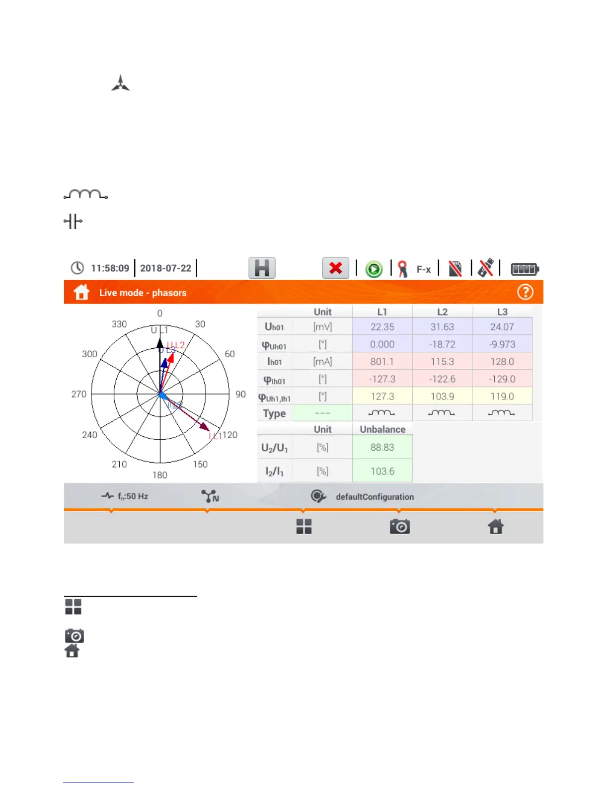
4.6.4 Vector diagram of fundamental components (phasor)
After the icon has been selected the phasor diagram appears (example in Fig. 4.16). It shows
the basic layout of component vectors of voltages and currents. It may be used to quickly verify the
correctness of connecting the recorder to the network.
The following tables are next to the diagram:
o the first, containing information on basic component values and their angles,
o the second, containing the unbalance coefficients of negative components (the coefficients
are only displayed for 3-phase networks).
The nature of the load is signalled by the icon of:
the coil (inductive load) if the angle between the fundamental components of the voltage
and current (φ
Uh1,Ih1
) is greater than zero (voltage is ahead of current),
the capacitor (capacitive load) if the angle φ
Uh1,Ih1
is negative (current is ahead of voltage).
Fig. 4.16. "Live" mode - phasor graph
Description of function icons
icon for selecting the view type. An additional menu appears, where type of view of the LIVE
mode can be changed
screenshot
return to the main menu of the recorder mode