During recording the HV LED / REC / CONT. diode flashes red at 2-second inter-
vals.
In order to avoid ambiguity in the calculating power values, attach clamps with their
arrows indicating the point of connecting L terminal of the meter to the tested object.
If they are attached in the other direction, an appropriate correction may be intro-
duced in the meter before recording starts (section 4.5.1).
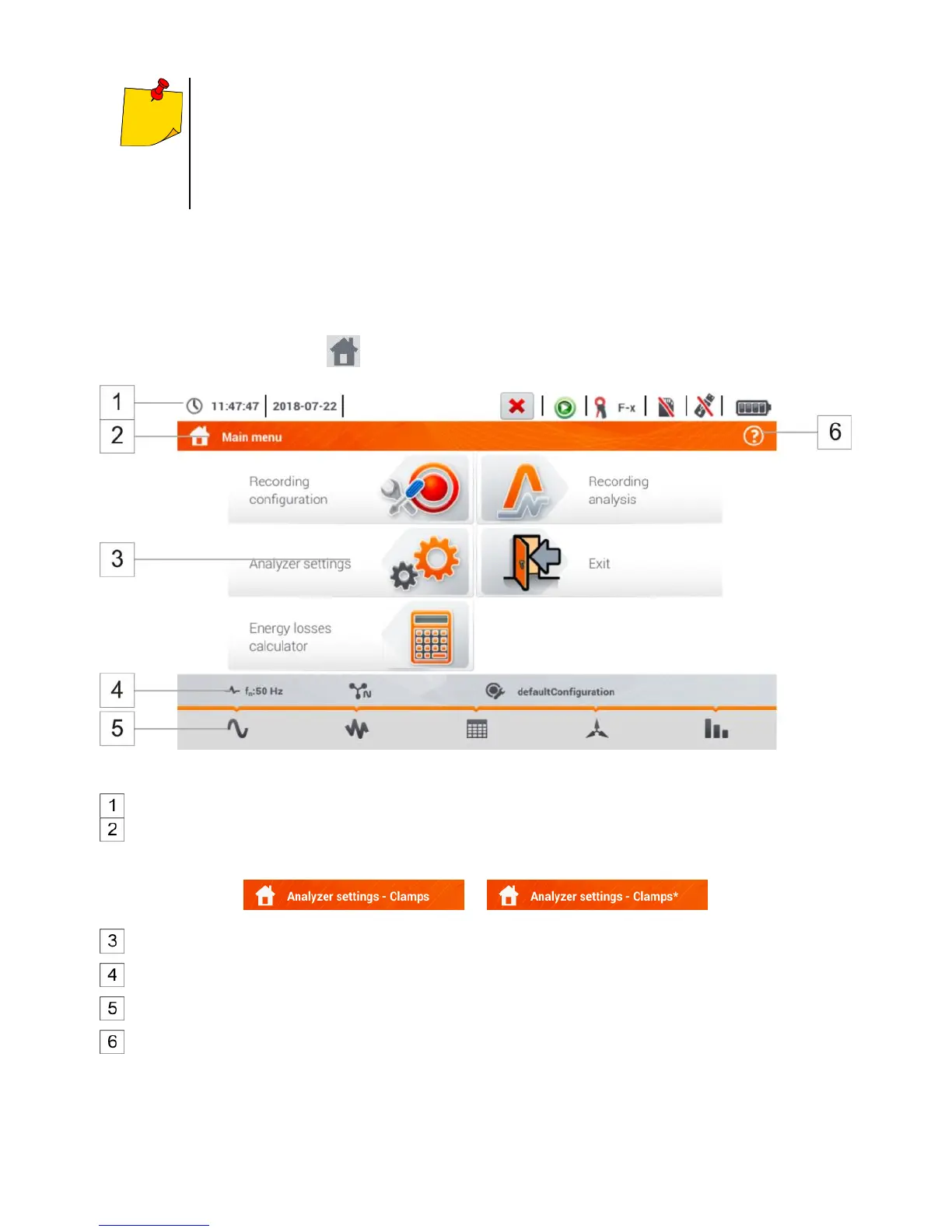
4.2 Main elements of the screen
After entering the recorder mode the Main menu is displayed. It is available:
after switching the meter on,
at any time after the icon has been selected on the display.
Fig. 4.2 Main elements of the recorder screen
Top bar
Name of the active menu
The fact of introducing a change that has not been saved yet is indicated by the * symbol in the
screen header.
Main window
Information bar on current network configuration ,
Function icons bar
Active menu help
Visualisation of connection systems
Explanation of icons