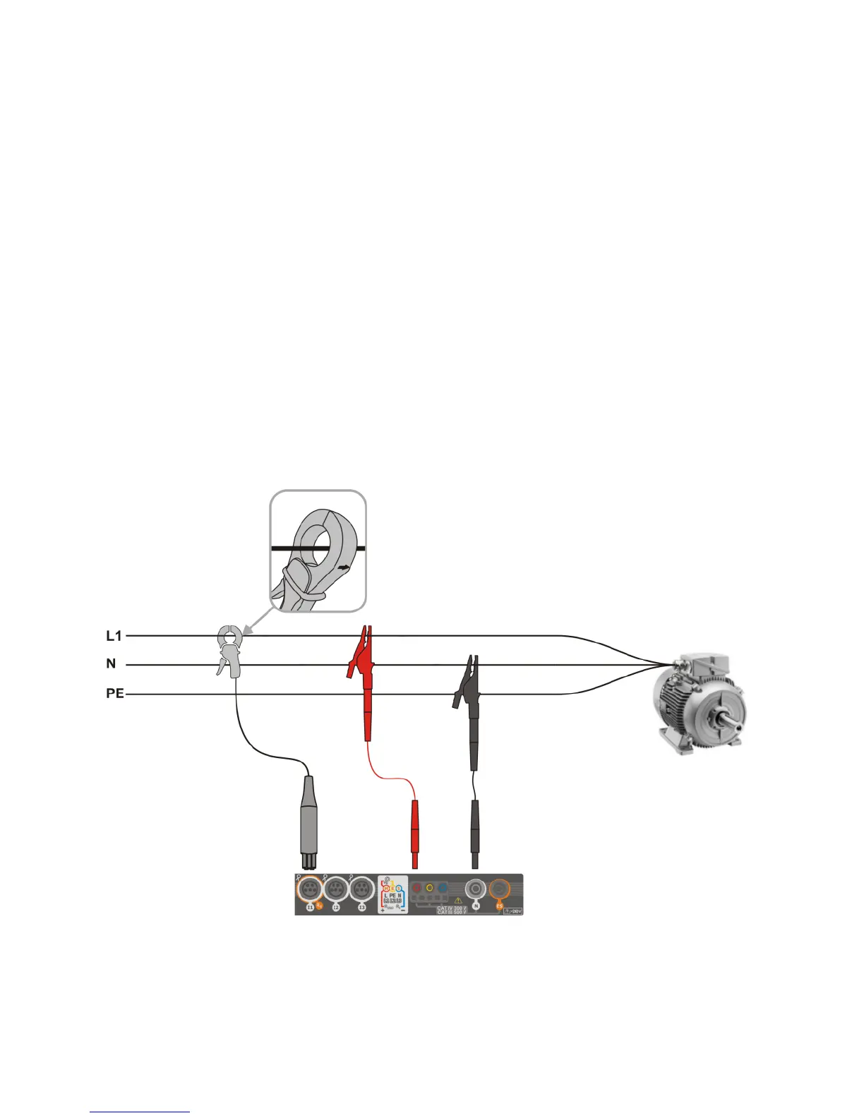
4.3 Connecting the measuring system
4.3.1 Measuring arrangements
The recorder may be connected directly to the following types of AC networks:
single-phase (Fig. 4.4)
2-phase (split-phase) with split-winding of the transformer) (Fig. 4.5),
3-phase 4-wire (Fig. 4.6),
3-phase 3-wire (Fig. 4.7, Fig. 4.8).
In three-wire AC systems, current may be measured by the Aron method (Fig. 4.8), which uses
only two clamps that measure linear currents I
L1
and I
L3
. I
L2
current is then calculated using the follow-
ing formula:
Pay attention to the direction of current clamps (flexible and hard). The clamps should be in-
stalled with the indicating the load direction. It may be verified by conducting an active power meas-
urement - in most types of passive receivers active power is positive. When clamps are inversely
connected, it is possible to change their polarity using in software (Analyzer settings Clamps)
The following figures show schematically how to connect the analyzer to the tested network de-
pending on its type.
Fig. 4.4 Wiring diagram – single phase