g) insulation type ............................................................................. double, according to EN 61010-1
h) measurement category according to EN 61010-1: .............................................................. III 300 V
i) dimensions: ........................................................................................................ 100 × 60 × 26 mm
j) weight: ....................................................................................................................... approx. 160 g
k) maximum diameter of tested cable: ................................................................................... 24 mm
l) length of clamp cables: .......................................................................................................... 1.5 m
m) operating temperature: ................................................................................................. 0C…+50C
n) relative humidity: ........................................................................................ 85% (non-condensing)
o) electromagnetic compatibility: ........................................................................................ EN 61326
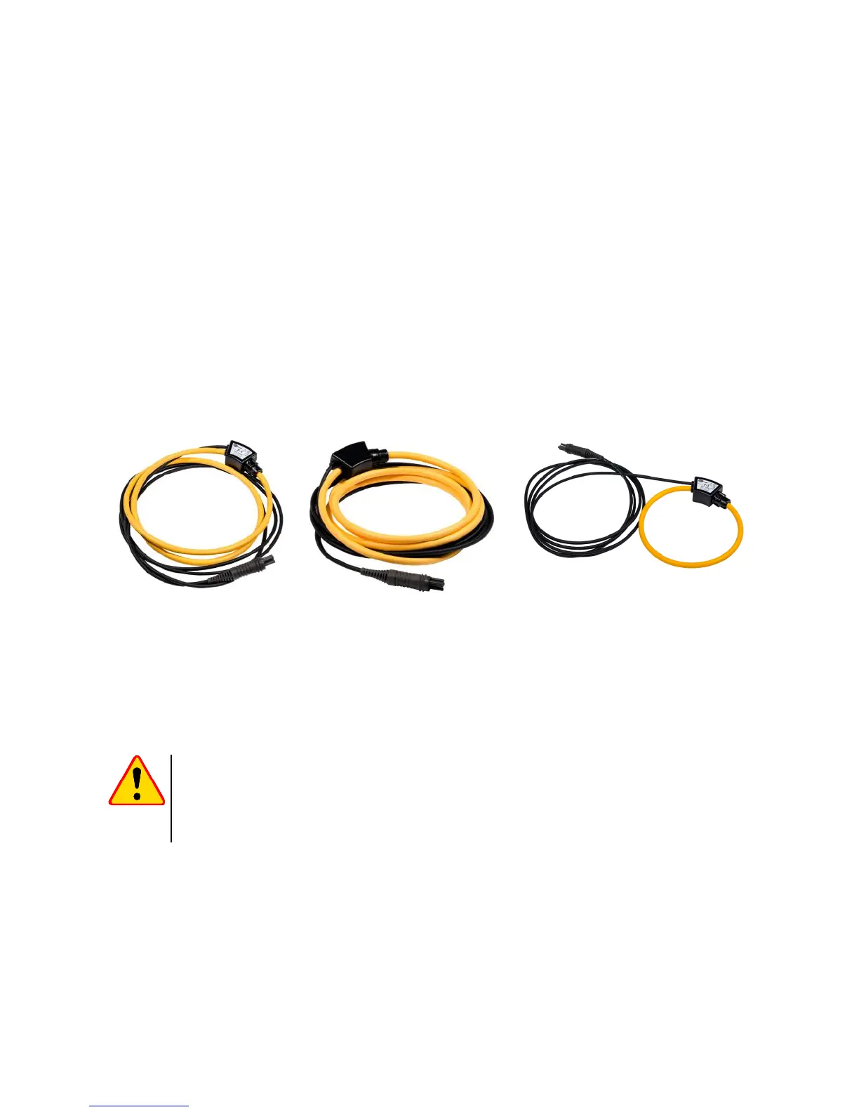
11.2.6 Clamps F-1A, F-2A, F-3A
Flexible clamps (Rogowski coil) F-1A, F-2A and F-3A are designed to measure AC currents with
frequencies up to 10 kHz for range 1 A…3000 A.
Flexible clamps F-1A, F-2A and F-3A are different only in terms of the coil perimeter. Electrical pa-
rameters are the same. The output signal is voltage proportional to the measured current derivative at
the sensitivity of 38.83 mV/1000 A for 50 Hz and 46.6 mV/1000 A for 60 Hz.
The output signal is conducted by a cable (2 m) ended with a pin adapted to the socket on the
meter.
The arrow marked on one of the clamps indicates the direction of current flow. It is assumed
that the current flows in the positive direction if it flows from the source to the receiver. This orienta-
tion of clamps is required for the correct power measurement.
Reference conditions
a) Temperature: ............................................................................................................... +18…+22°C
b) Conductor position................................................................... conductor centred in the clamp loop
c) Permanent magnetic field .............................................................. <40 A/m (Earth's magnetic field)
d) Variable, external magnetic field ............................................................................................. none
e) External electric field .............................................................................................................. none