4.3.2 Verifying the connection
Selecting the top bar icon signalling the correct connection of the recorder (Fig. 4.3 element ) a
window is displayed showing some important information on the connection of the recorder to the
tested network. This information helps the user to verify the compliance of the current configuration
of the recorder with the parameters of the measured network.
Voltage values – two possible icons:
RMS voltages are correct, they are within the tolerance range of 15% of the nominal
voltage,
RMS values are outside the range of U
nom
15%.
Current values – four options:
RMS currents are in the range of 0.3% I
nom
…115% I
nom
,
RMS currents are lower than 0.3% I
nom
,
RMS currents are higher than 115% I
nom
,
--- dashes are displayed when the current measurement is disabled in the configuration.
Voltage vectors – the recorder verifies the correctness of the basic angles and displays the
corresponding icon:
the vectors have correct angles in the range of 30 of the theoretical value for a resistive
load and symmetrical circuit (in 3-phase systems),
the accuracy of angles cannot be verified, because the RMS voltage value is too low (less
than 1% of U
nom
),
incorrect angles of vectors. In three-phase systems, this icon is displayed, among others,
in case of reversed sequence of voltage phases.
Current vectors – correctness of vector angles is verified for the components of main currents
in relation to the voltage vectors. The following icons are displayed:
vectors are within 55 in relation to angles corresponding to the voltage vectors,
the accuracy of current vector angles cannot be verified, because the RMS current values
are too low (below 0.3% of I
nom
),
vectors are outside the acceptable range of angles ( 55),
--- dashes are displayed when the current measurement is disabled in the configuration
Frequency:
the measured grid frequency is in the range of f
nom
10%,
the RMS value of reference voltage phase is lower than 10V or there is no PLL synchroni-
zation,
the measured frequency is outside of f
nom
10%.
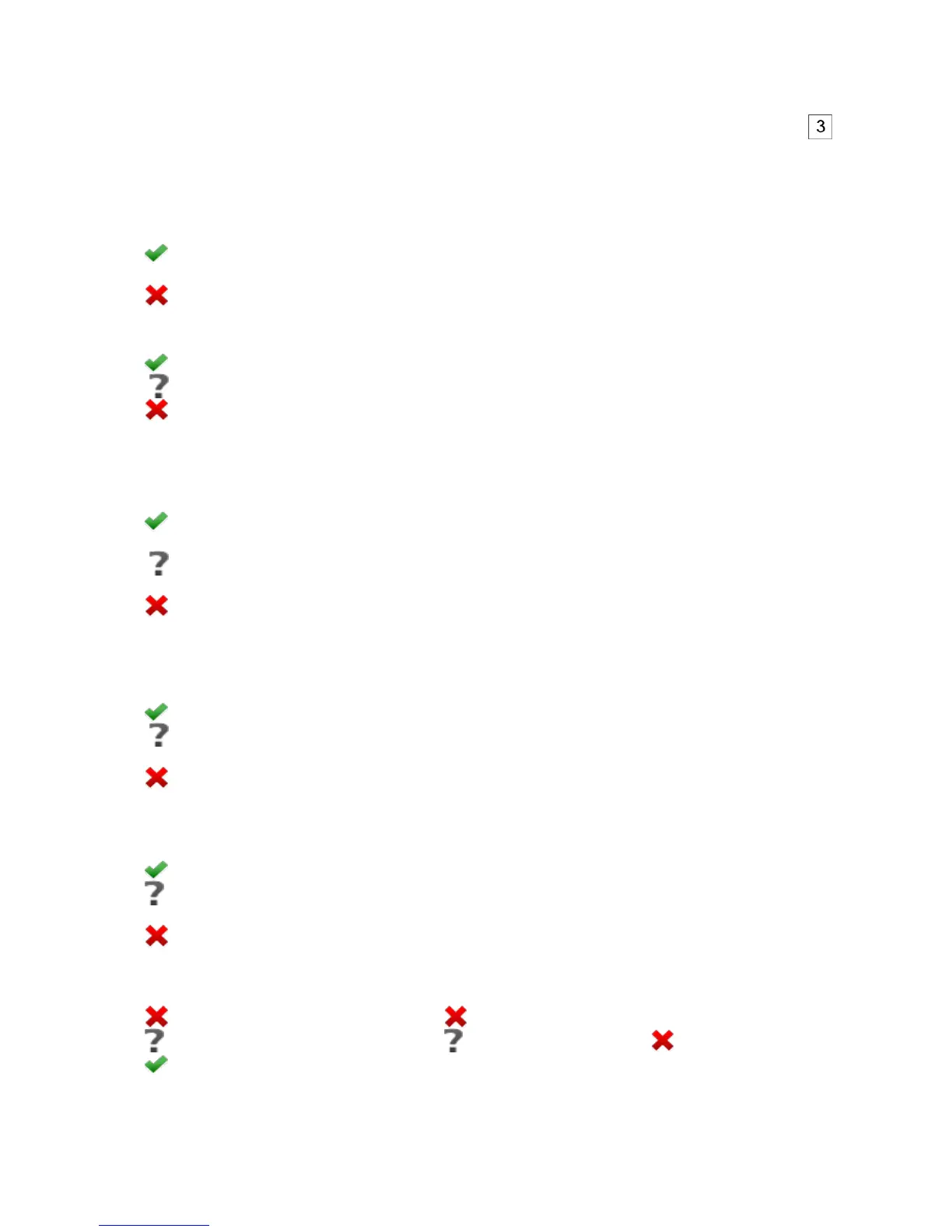
The icon is displayed in the top control bar in the following way:
if the table includes is at least one ,
if the table includes is at least one , but there is no error (no ),
if all measured parameters are correct.