3.7.4 Measurements in IT networks
Before performing measurements select the appropriate network type in the main menu (menu
Measurement settings, section 2.2.1).
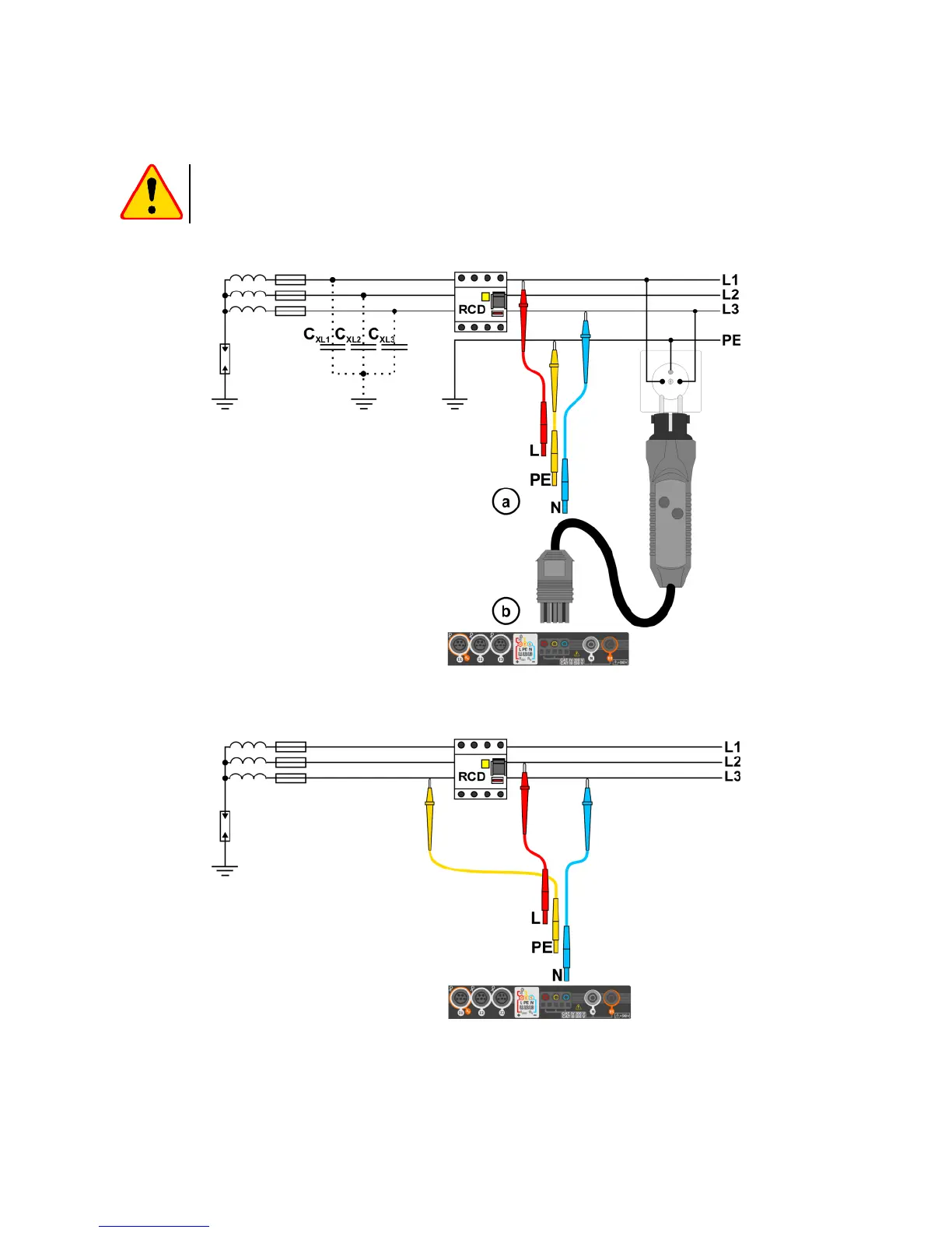
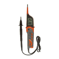
The manner of connecting the device to the installation is shown in Fig. 3.8 and Fig. 3.9.
Fig. 3.8 RCD measurement in the IT network. The circuit is closed by the parasitic
capacitances C
x
Fig. 3.9 RCD testing without the PE conductor
The manner in which the measurements of current and the RCD triggering time has been de-
scribed in section 3.7.2, 3.7.3.
Operating voltage range: 95 V … 270 V.