6-16
DSR-70/70P
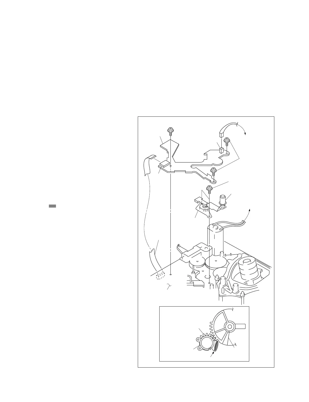
Fig.-1
CN462
CN1
SE-462 board
Precision screw (P 1.4x3.5)
Roller
S tension regulator
assembly
Flexible
card wire
DR-364 board
Gear
Grease
TR limiter gear
Precision screw
(P 1.4x3.5)
S tension regulator
assembly
6-11. SUPPLY TENSION REGULATOR ASSEMBLY REPLACEMENT
Tools
Cleaning cloth : 3-184-527-01
Cleaning fluid : 9-919-573-01
Reference plate : J-6442-990-A
Guide gauge : J-6442-420-A
Mode
EJECT
Removal
1. Remove the S4 arm assembly.
(Refer to section 6-13.)
2. Remove CN462 and CN1 from the SE-462
board, and remove the SE-462 board by
removing the three precision screws.
3. Remove the two screws from the MD chassis and
remove the tension regulator assembly.
Attachment
4. Engage the gear of the new tension regulator
assembly with the TR limiter gear as shown in
Fig.-1.
5. Coat the area of the S tension regulator
assembly with grease. (Fig.-1)
6. Set the DSR-70/70P to the threading state.
7. Check that the tape guides are not slanted and
bent. (Refer to section 6-11-1.)
8. Check height of the tape guides.
(Refer to section 6-11-1.)
9. Clean the roller using the cleaning cloth
moistened with cleaning fluid.
Adjustment After Replacement
. Perform the tape tension adjustment.
(Refer to section 4.)
. Perform the tape path adjustment.
(Refer to section 7.)
 Loading...