6-15
DSR-70/70P
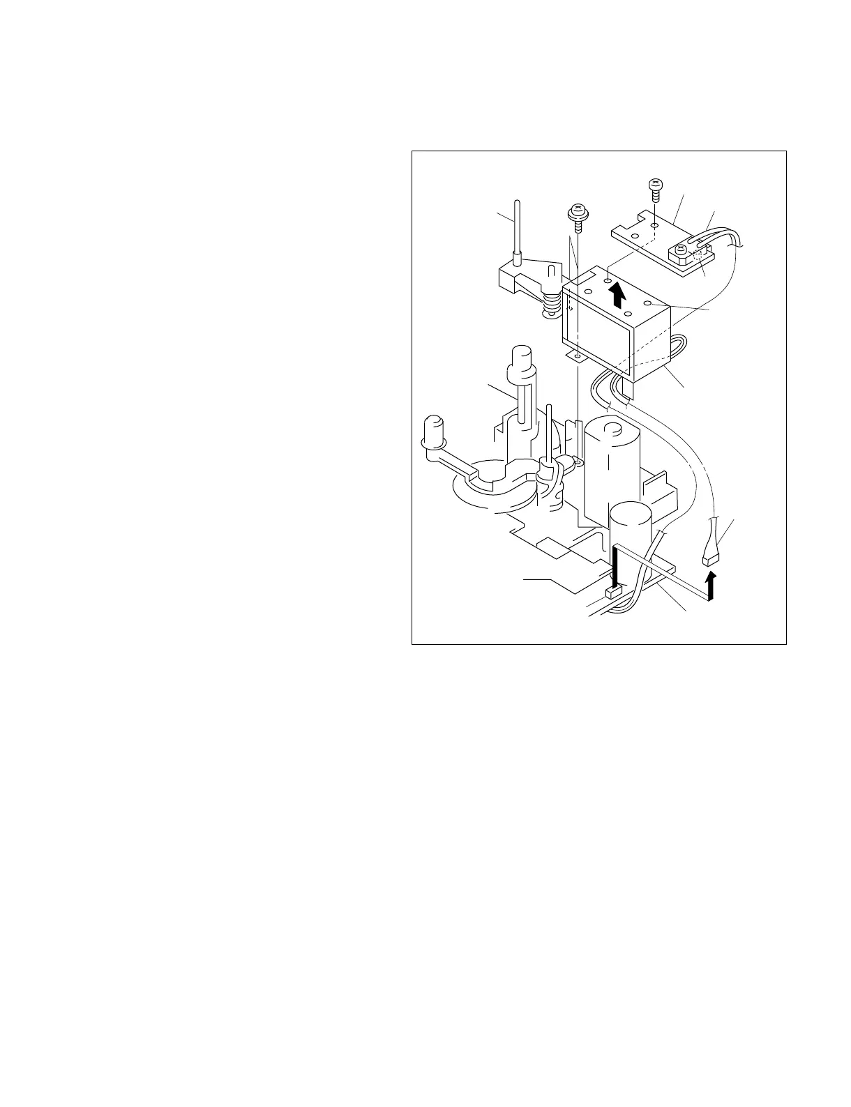
P 2.6x4
CN486
Shaft
Precision screw
(1.4x3.5)
DEW sensor
Harness
DR-364 board
Heat sink
Pinch solenoid
assembly
Positioning
hole
Protrusion
6-10. PINCH SOLENOID ASSEMBLY REPLACEMENT
Removal
1. Remove the pinch roller. (Refer to section 6-9.)
2. Remove the connector (CN486) from the DR-
364 board.
3. Remove the screw (P 2.6x4) and remove the
heat sink.
4. Remove the two precision screws (1.4x3.5) and
remove the pinch solenoid assembly in the
direction of the arrow.
Attachment
5. Insert the shaft of the new pinch solenoid
assembly into the hole of the pinch arm limiter,
align the two holes with the position setting pin
of the MD chassis and fix them with the two
precision screws (1.4x3.5).
Note : Carefully route the harness around
the pinch solenoid assembly so that it
is not pinched by any parts.
6. Insert the harness of the pinch solenoid into the
DR-364 board (CN486).
7. Align the heat sink positioning protrusion with
the positioning hole of the pinch solenoid
assembly, and secure them by the screw
(P 2.6x4).
Adjustment After Replacement
8. Perform the tape path check/adjustment.
(Refer to section 7.)