6-28
DSR-70/70P
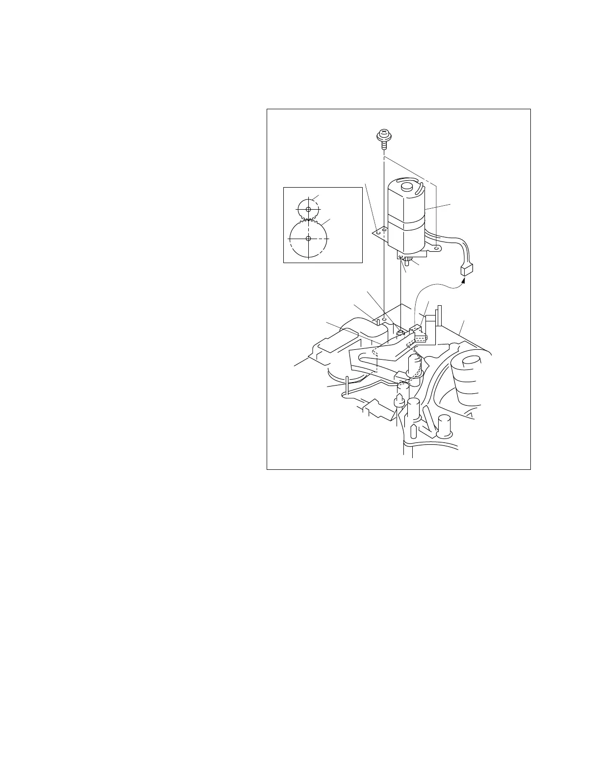
Fig.-1
CN1
Precision screw (1.4x3.5)
Threading motor
assembly
Motor gear
Motor gear
Hole
MD chassis
FG gear
assembly
Positioning pin
SE-462 board
Positioning hole
Shaft of FG gear assembly
6-19. THREADING MOTOR REPLACEMENT
Removal
1. Remove the connector (CN1) from the SE-462
board.
2. Remove the two precision screws from the MD
chassis and remove the threading motor
assembly.
Attachment
3. Coat the entire gear surface of the new threading
motor assembly with grease.
4. Insert the hole of the threading motor assembly
into the positioning pin of the MD chassis.
Engage the motor gear with the FG gear
assembly. Insert the positioning hole into the
shaft of the FG gear assembly. (Fig.-1)
Note :
..
..
. At this moment, attach the
threading motor while pushing in
the manual gear.
..
..
. Be sure not to pinch the SE-462
board.
5. Fix the threading motor assembly to the MD
chassis with the two precision screws.
 Loading...