Chapter 7 Setup Menu
112
Chapter 7 Setup Menu
Extended Menu
Extended Menu Operations
To use the extended menu, set basic menu item 999
MENU GRADE to ENHAN beforehand.
In the extended menu, you can carry out the same
operations as in the basic menu except setting of sub-
items.
To set sub-items
Operate as follows.
1
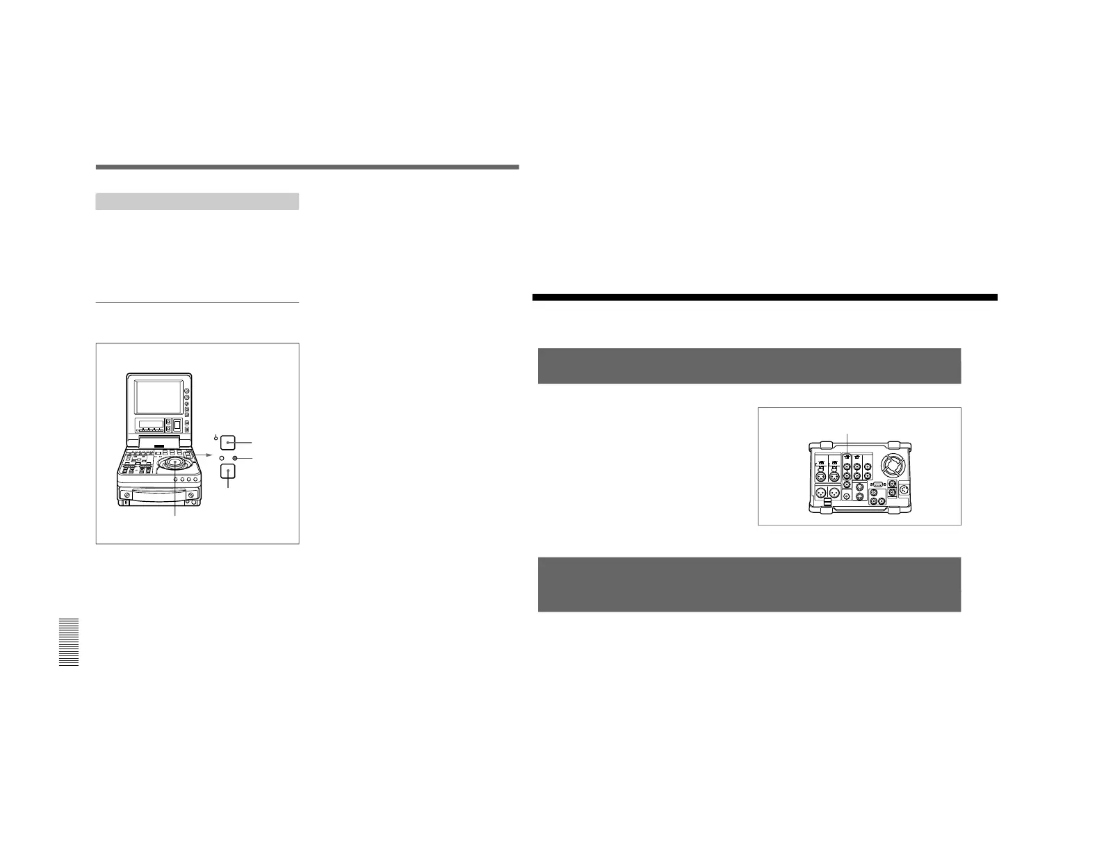
Confirm the JOG indicator lights. If not, set the
unit to jog mode by pressing the jog dial.
2
Select the desired menu item.
For information about how to select a menu item, see
the section “Changing the currently displayed menu
item” (page 104).
3
Holding down the STOP button, turn the jog dial to
select the desired sub-item.
4
Holding down the search button, turn the jog dial
to change the value for the selected sub-item.
Chapter 8 Connections and Settings
Chapter 8 Connections and Settings
113
Chapter
8
Connections and
Settings
Reference Video Signals for Analog Signal Editing
In order to provide stable video and audio signals for
analog editing, it is necessary for the built-in time base
corrector (TBC) to operate correctly. To ensure this,
input a reference video signal synchronized with the
video signal to the REF. VIDEO IN connector and set
the REF. VIDEO IN 75 Ω termination switch to ON.
Connections for Cut Editing Using i.LINK Interface
(Optional DSBK-140 Required)
Using two DSR-70/70P units, each fitted with the
optional DSBK-140 board, as a pair of player and
recorder, you can configure a cut editing system.
For connections and settings, see the section “Connections
for Cut Editing Using Two DSR-70/70P Units” on page 36.
REF. VIDEO IN connector
and 75 Ω termination switch