Settings for Editing
Chapter 3 Editing
38
Chapter 3 Editing
Settings for Editing
When using two units of the DSR-70/70P as a pair of recorder and player
in an editing system, set the recorder and player as follows. Basically, the
same recorder settings and player settings apply when you use a DSR 70/
70P unit as a stand-alone recorder or player.
Recorder Settings
Make settings as follows.
1
Set the REMOTE/LOCAL switch to LOCAL.
2
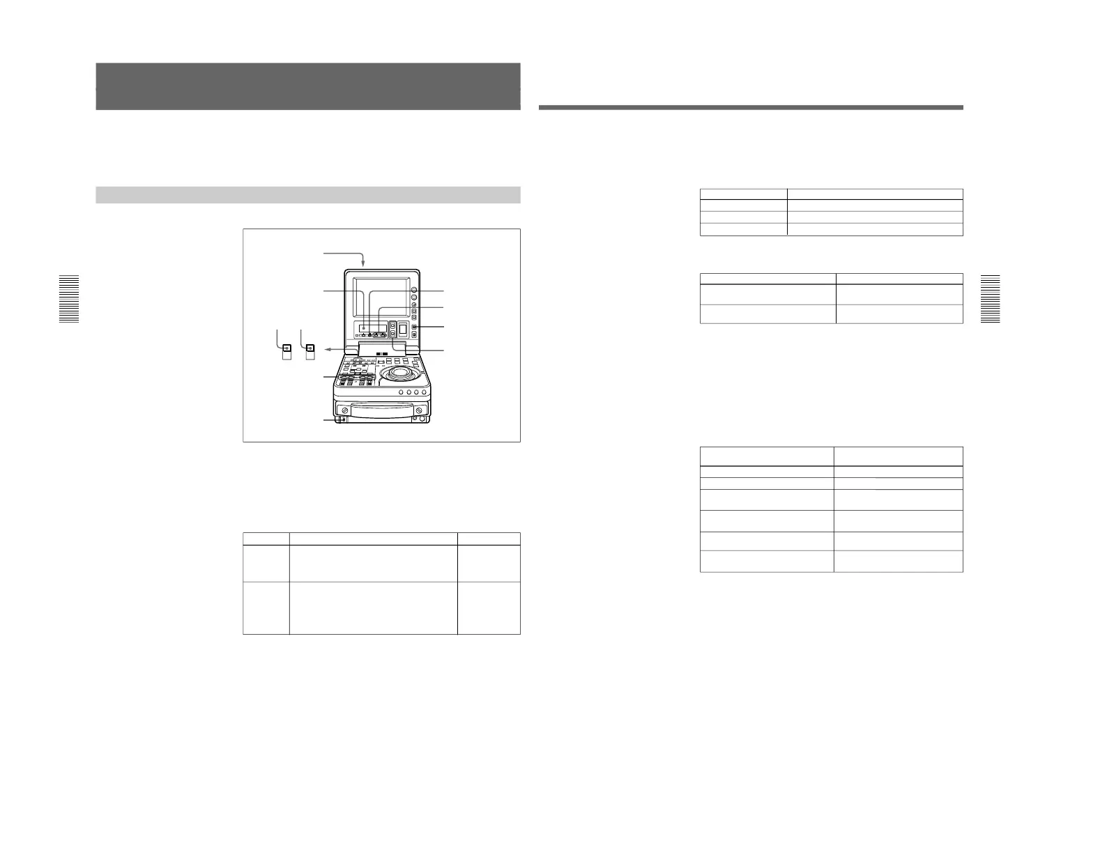
Set the POWER switch to ON, then make the following checks.
When the unit is powered, the POWER indicator lights and the sub
LCD home page appears in the sub LCD.
POWER indicator
Sub LCD
UP/DOWN buttons
Check Indication/What to do
See for details
Enough
battery
power
remaining?
Check the remaining battery power indication.
If “BATT” is flashing
Replace the battery.
“
5
Remaining
battery power
indication” (page
67)
If “HUMID!” is displayed
Leaving the unit powered, wait until the message
disappears.
(In this case, the alarm message “MOISTURE
HAS BEEN DETECTED” also appears on the
LCD monitor.)
No
condensation
in the unit?
“Condensation”
(page 127)
Chapter 3 Editing
Chapter 3 Editing
39
3
Use the COUNTER SELECT button to select the type of time data to
be used.
Each press of the button cycles through three options in the sub LCD:
CNT, TC, and UB.
4
When the time data selected in step 3 is timecode (TC), use the TC
INT/EXT switch to select the type of timecode.
5
Select the formats of video and audio input signals to be used.
If any signal not connected to the unit is selected, the corresponding
signal indication in the sub LCD flashes.
To select an input video signal format
Press the sub LCD operation button F4, highlighting the input video
signal indication, then press the UP button or the DOWN button
repeatedly until the input video signal indication corresponding to the
desired video signal appears in the sub LCD.
a) When using the component signals (CMPNT), set the IN/OUT switch of
the DSBK-170 to IN.
Selecting the i.LINK (DV) or SDTI (QSDI) signals for input video
causes the same to be automatically selected also for input audio.
Selectable time data Time data indication in the sub LCD
Count in the counter CNT
Timecode TC
User bit data UB
Selectable video signals
(Input connectors)
Composite signals (VIDEO INPUT)
S-video signal (S VIDEO IN)
i.LINK (DV) signals (DV IN/OUT
(optional DSBK-140))
SDTI (QSDI) signals (SDTI(QSDI) IN
(optional DSBK-150))
SDI signals (SDI IN (optional DSBK-
160))
Component signals (Y, R–Y, B–Y
(optional DSBK-170))
Input video signal indication in the
sub LCD
CMPST
S VIDEO
i.LINK
SDTI
SDI
CMPNT
a)
Selectable timecode TC INT/EXT switch setting
Timecode generated by the internal
timecode generator
External timecode input to the TC IN
connector
INT
EXT
(Continued)
 Loading...