Settings for Editing
Chapter 3 Editing
40
Chapter 3 Editing
To select an input audio signal format
Press the sub LCD operation button F3, highlighting the input audio
signal indication, then press the UP button or the DOWN button
repeatedly until the input audio signal indication corresponding to the
desired audio signal appears in the sub LCD.
Selecting the i.LINK (DV) or SDTI (QSDI) signals for input audio
causes the same to be automatically selected also for input video.
Cut editing using i.LINK
When using a cut editing system as illustrated in the section
“Connections for Cut Editing Using Two DSR-70/70P Units
— i.LINK connections” on page 36, select “i.LINK” for input video
and audio.
6
Select the audio recording mode.
Press the sub LCD operation button F2, highlighting the audio
recording mode indication, then press the UP button or the DOWN
button so that the audio recording mode indication corresponding to
the selected mode appears in the sub LCD.
Notes
• In the DVCAM format, there are two audio recording modes, that is,
two channel, 48-kHz mode and four-channel, 32-kHz mode. It is not
possible to select other modes (for example, four-channel, 48-kHz
mode).
• If an audio signal in a different mode than the base tape is used in
assemble or insert editing, the signals will be discontinuous at the edit
points and correct editing will not be obtained. For this reason, audio
editing between different modes is inhibited on this unit.
For smooth editing operations, check the audio recording mode of the
base tape beforehand. If on a tape there is a point where the audio
mode is switched, you cannot perform an insert editing on that point.
• Once you have started recording, you cannot change the audio mode
selection.
Selectable audio signals
(Input connectors)
Analog signals (AUDIO INPUT CH-1/
CH-2)
i.LINK (DV) signals (DV IN/OUT
(optional DSBK-140))
SDTI (QSDI) signals (SDTI(QSDI) IN
(optional DSBK-150))
SDI signals (SDI IN (optional
DSBK-160))
Input audio signal indication in
the sub LCD
ANALOG
i.LINK
SDTI
SDI
Selectable audio recording mode Indication in the sub LCD
Two-channel, 48-kHz recording mode
Four-channel, 32-kHz recording mode
2/48k
4/32k
Chapter 3 Editing
Chapter 3 Editing
41
7
Use the AUDIO INPUT PRESET/VARIABLE switch and the AUDIO
INPUT CH 1 to CH-4 level adjustment knobs to adjust the audio input
levels.
Watching the audio level meter, adjust the levels so that the meter does
not indicate higher values than 0 dB when the audio signals are at their
maximum.
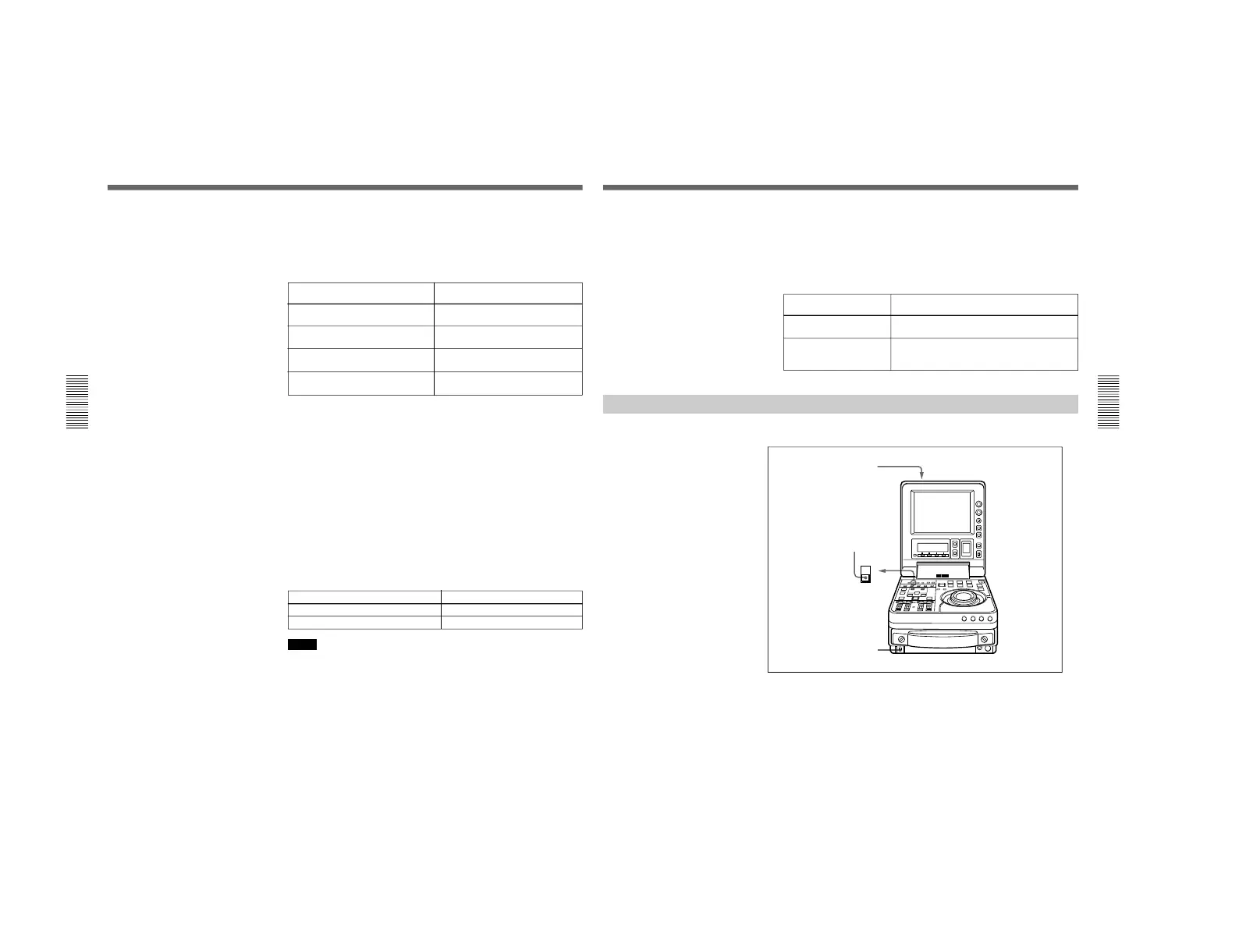
Player Settings
Make settings as follows.
1
Set the REMOTE/LOCAL switch to REMOTE.
PRESET
VARIABLE
Preset to fixed levels. Levels cannot be adjusted
with the level adjustment knobs.
Levels adjustable with the level adjustment
knobs. Adjust the levels while viewing the audio
level meter in E-E mode.
AUDIO INPUT PRESET/
VARIABLE switch setting
Audio input level adjustment



 To Next Page