1-37
DSR-70/70P
72
Chapter 4 Time Data and Sub LCD Menu
Chapter 4 Time Data and Sub LCD Menu
Input and Output Settings for Video and Audio Signals –– Sub LCD Menu
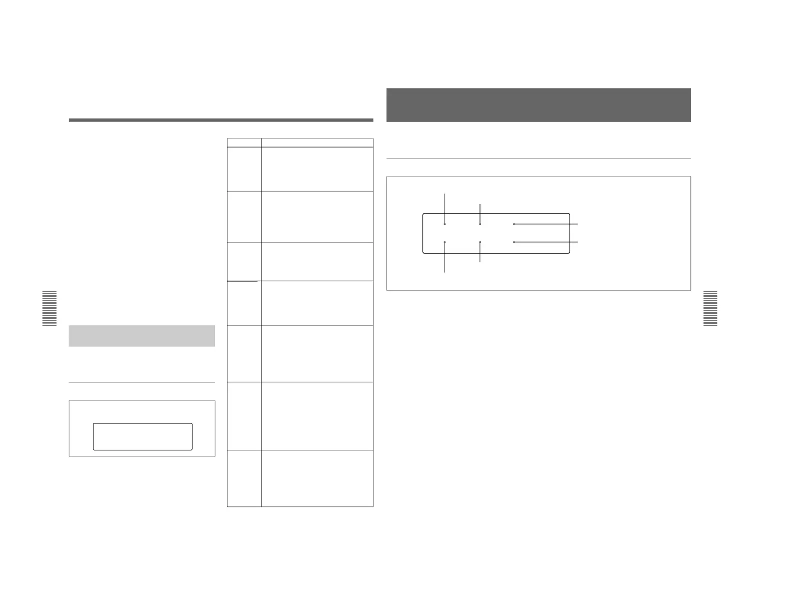
Input mixing settings page
By pressing F1 to F3, you can make the following
three settings for mixing of input signals in audio
channels 1 and 2. The selected setting is highlighted.
To select input signals, use audio settings page 1-2.
MIX OFF: Assign IN-1 to channel 1, and assign IN-
2 to channel 2.
1+2 → 1: Assign mixed signals of IN-1 and IN-2 to
channel 1, and assign IN-2 to channel 2.
1+2 → 2: Assign IN-1 to channel 1, and assign mixed
signals of IN-1 and IN-2 to channel 2.
Output monitor settings page
By pressing F1 to F3, you can make the following
three settings for monitor output signals. The selected
setting is highlighted.
1: Assign channel 1 to monitor output.
2: Assign channel 2 to monitor output.
1+2: Assign mixed signals from channels 1 and 2 to
monitor output. (This corresponds to the
MONITOR item setting “METER” in audio
settings page 1-3.)
Making Settings in the Video
Settings Pages
The following tables show the items that can be set in
the video settings pages.
Video settings page
PP SIZE
1/9
ZEBRA
OFF
MONITOR
OUTPUT
PROCESS
CONTROL
PANEL
PP MODE
OFF
WIDE
AUTO
PP POSI.
4
Item Setting
When composite video (CMPST) has been
selected for input, select the E-E signal for
output to the LCD monitor of the unit.
INPUT: Input video E-E with no digital
process delay is output.
OUTPUT: Output video E-E with a digital
process delay is output
Select how to display two input pictures on
the LCD monitor.
OFF: Not displaying two pictures.
1: Picture-in-picture display
2: Two pictures reduced and displayed side
by side
3: Side-by-side display reduced in horizontal
direction only
Select the size of the smaller picture to be
inset for picture-in-picture display on the LCD
monitor.
1/16:
1
/
16
the normal size
1/9:
1
/
9
the normal size
1/4:
1
/
4
the normal size
Select the position of the smaller picture to
be inset for picture-in picture display on the
LCD monitor.
1: Upper left position
2: Upper right position
3: Lower left position
4: Lower right position
Select what to use to control the following
items: SETUP (when using the setup menu)
or PANEL (when using the front control
section).
• Video output level
• Chroma signal output level
• Setup level (DSR-70)/black level (DSR-
70P)
• Chroma phase
Select whether to record/play back video with
wide-screen aspect ratio information
requiring the LCD monitor to switch to 16:9
mode.
AUTO: The LCD monitor automatically
switches to 16:9 mode when wide screen
video is input or played back.
ON: The LCD monitor is always in 16:9
mode.
OFF: The LCD monitor does not switch to
16:9 mode.
Set the zebra pattern to be displayed in the
LCD monitor.
OFF: Do not display.
50%: Display zebra pattern with 50% or more
video level.
80%: Display zebra pattern with 80% or more
video level.
100%: Display zebra pattern with 100% or
more video level.
a) Displayed only when the DSBK-180/180P Dual Video Input
Board installed
MONITOR
a)
PP
MODE
a)
PP SIZE
a)
PP POSI.
a)
PROCESS
CONTROL
WIDE
ZEBRA
Chapter 4 Time Data and Sub LCD Menu
Chapter 4 Time Data and Sub LCD Menu
73
General Settings Pages of the Sub LCD Menu
There are general settings pages (1) and (2).
General settings page (1)
1 PRESET/REGEN (regenerate) setting
Selects the value set in the internal timecode generator.
PRESET: Preset the initial value of the timecode
generated by the internal timecode generator,
either by a control panel operation or by remote
control from the device connected to the
REMOTE connector.
REGEN: Synchronize the internal timecode
generator with the timecode read by the internal
timecode reader.
2 F-RUN/R-RUN (free-run/rec-run) setting
Selects the progression method for the timecode
generated by the internal timecode generator.
F-RUN: Timecode progresses continuously from the
time when this unit is powered on, regardless of
the unit's operating status.
R-RUN: Timecode progresses only during recording.
3 DF/NDF (drop-frame/non-drop-frame) setting
(for DSR-70 only)
Selects DF to advance timecode in drop-frame mode,
and NDF to advance timecode in non-drop-frame
mode.
4 KEY INH (key inhibit) setting
Set to ON to disable the buttons on the control panel.
(Sub LCD menu operations can still be performed
even when this item is set to ON.)
You can select the buttons that are disabled under
setup menu item 118.
If you try to operate the disabled buttons, the message
“!!KEY INH.!” appears in the time data display area
on the sub LCD.
5 PB/EE (monitor signal) setting
Selects the video/audio signal output when the tape is
being fast forwarded or rewound, or when the unit is
stopped or on standy .
PB: Playback signal
PB/EE: Input signal in E-E mode
6 REMOTE setting
When the REMOTE/LOCAL switch is set to
REMOTE, selects the source for control of this unit.
9P: The unit is controlled from the device connected
to the REMOTE connector (D-sub9-pin).
i.LINK: The unit is controlled from the device
connected to the DV IN/OUT connector (DSBK-
140).
To switch to general settings page (2)
Press the PAGE button.
3 DF/NDF (drop-frame/non-drop-frame) setting
(for DSR-70 only)
TC GENERATOR
PRESET
KEY INH
OFF
F-RUN
EE/PB
PB
DF
REMOTE
9P
1 PRESET/REGEN (regenerate) setting
2 F-RUN/R-RUN (free-run/rec-run) setting
5 PB/EE (monitor signal) setting
4 KEY INH (key inhibit) setting
6 REMOTE setting