1-62
DSR-70/70P
Chapter 8 Connections and Settings
122
Chapter 8 Connections and Settings
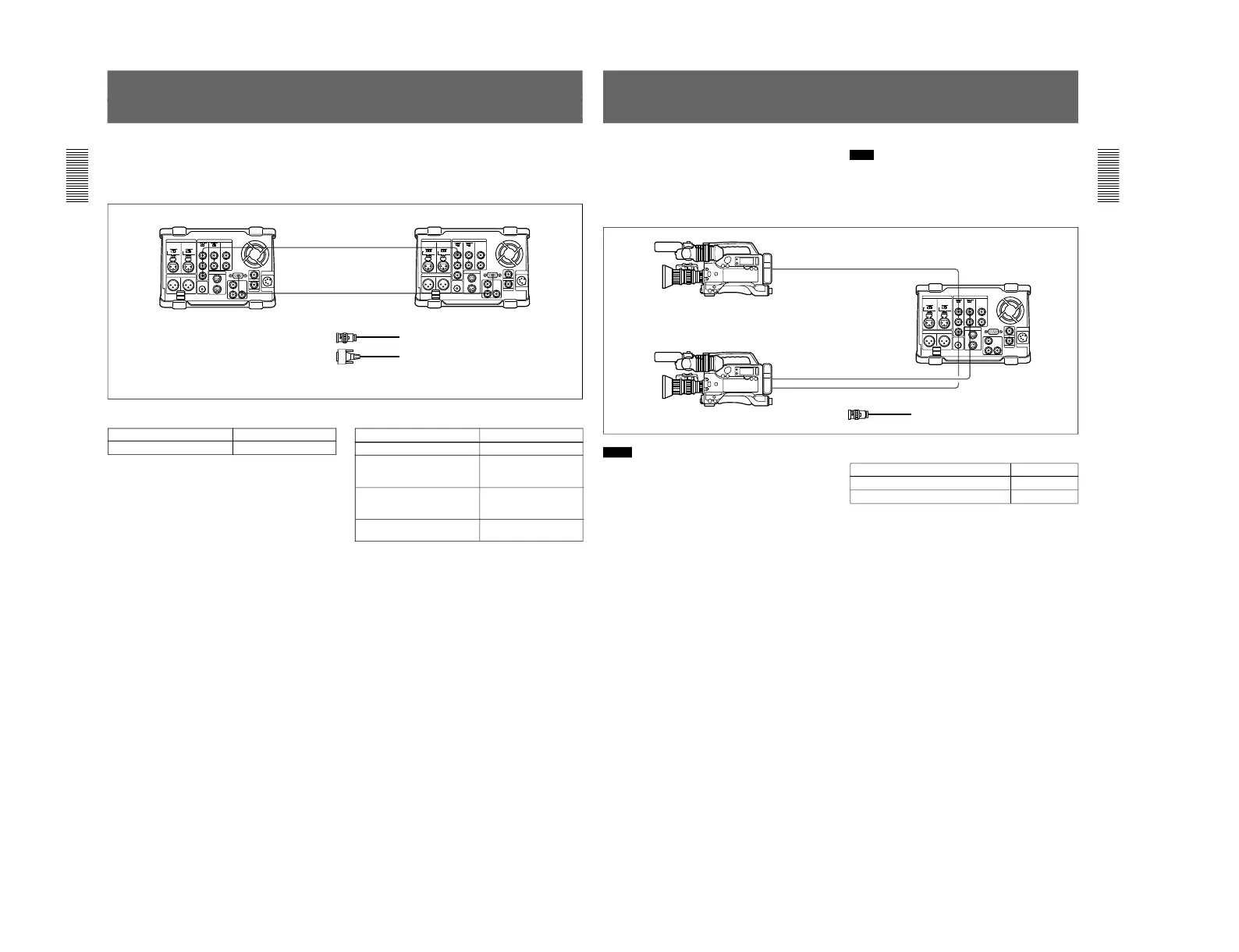
Connections for Two-Unit Synchronous Playback
The following shows connections for synchronous
playback using two DSR-70/70P units.
In the following, the controlling unit is referred to as
the recorder and the controlled unit as the player.
For information about how to carry out two-unit
synchronous playback, see the section “Two-Unit
Synchronous Playback” on page 89.
REMOTEREMOTE
REF.
VIDEO
OUT
REF.
VIDEO
IN
Player settings
Switch/menu Setting
REMOTE/LOCAL switch REMOTE
Recorder settings
Switch/menu
Setting
REMOTE/LOCAL switch LOCAL
Setup menu item 004 ON (Synchronize.)
OFF (Do not
synchronize.)
Setup menu item 305
(When synchronizing,
synchronization accuracy)
ACCUR (±0 frame)
ROUGH (±1 frame)
REF. VIDEO IN 75 Ω
termination switch
ON
DSR-70/70P (player) DSR-70/70P (recorder)
1
2
1 75 Ω coaxial cable (not supplied)
2 RCC-5G/10G/30G 9-pin remote control
cable (length 5 m (16 ft)/10 m (33 ft)/30 m
(98 ft), not supplied)
Chapter 8 Connections and Settings
Chapter 8 Connections and Settings
123
Connections for Two-Input Switched Video
Recording
(Optional DSBK-180/180P Required)
You can use the DSR-70/70P in combination with two
DSR-300/300P or other camcorders, for two-input
switched video recording.
The following figure shows the connections in this
case.
Note
In this case, the DSBK-180/180P Dual Video Iuput
Board is required.
For information about how to carry out two-input switched
video recording, see page 82.
REF. VIDEO OUT
VIDEO OUT
GEN LOCK IN
VIDEO OUT
REF. VIDEO IN
VIDEO INPUT
DSR-300/300P
DSR-70/70P
DSR-300/300P
1
1
1
1 75 Ω coaxial cable (not supplied)
Notes
•The video signals output from the two camcorders
must be synchronous. Make sure at least one of the
two camcorders used has the Gen-lock (generator
lock) function.
•When using a camcorder without the Gen-lock
function, connect its output video to the REF. VIDEO
IN connector of this unit.
•When long cables are used to connect two
camcorders to this unit, a slight shift in phase
between the video signals input from them may
result.
For information about how to make phase adjustment in
such a case, see the section “To adjust the output video
signal phases” on page 83.
DSR-70 settings
Switch Setting
REF. VIDEO IN 75 Ω termination switch ON
VIDEO INPUT 75 Ω termination switch ON