1-58
DSR-70/70P
Chapter 8 Connections and Settings
114
Chapter 8 Connections and Settings
Connections for Digital Nonlinear Editing Using
SDTI (QSDI) Interface
(Optional DSBK-150 Required)
This unit can be connected to an ES-7 EditStation to
configure a digital non-linear editing system. Using the
SDTI (QSDI) interface, you can transfer video, audio,
timecode, and other compressed data between this unit
and the ES-7.
The unit supports ClipLink functions, enabling index
pictures recorded on tape and ClipLink log data stored
in cassette memory to be transferred to the ES-7 in an
instant.
For an overview of the ClipLink function, refer to the
separate ClipLink Guide.
The following is a connection diagram for digital non-
linear editing system in which this unit serves as the
recorder.
For connections of the ES-7’s peripheral devices (the
control panel, the disk unit, etc.) and the player, refer
to your ES-7 Operating Instructions.
Note
In this case, the DSBK-150 SDTI (QSDI) Iuput/Output
Board is required.
REF. VIDEO IN
REMOTE
STDI(QSDI) IN
STDI(QSDI) OUT
BB OUT
RECORDER
QSDI OUTPUT
QSDI INPUT
ES-7
DSR-70/70P (recorder)
1
2
1
1
Settings on the DSR-70/70P
Switch
REMOTE/LOCAL
REF. VIDEO IN 75Ω termination
Setting
REMOTE
ON
1 75 Ω coaxial cable (not supplied)
2 RCC-5G/10G/30G 9-pin remote control cable
(length 5 m (16 ft)/10 m (33 ft)/30 m (98 ft), not
supplied)
Chapter 8 Connections and Settings
Chapter 8 Connections and Settings
115
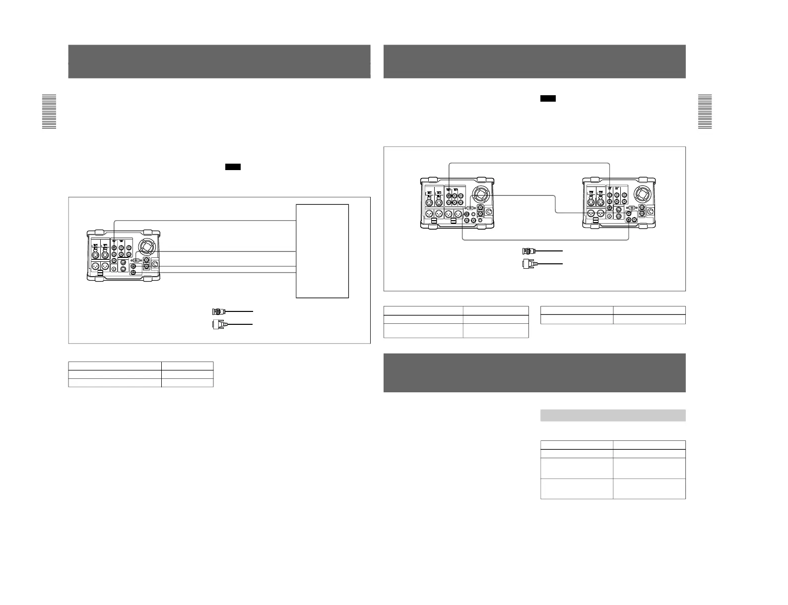
Connections for Cut Editing Using SDI Interface
(Optional DSBK-160 Required)
For a cut editing system using this unit together with a
DNW-A25/A25P Betacam SX VCR using an SDI
connection, the following figure shows an example of
the connections. In this example, the DNW-A25/A25P
is used as the recorder and this unit is used as the
player.
DNW-A25/A25P settings
DNW-A25/A25P (recorder)
REF. VIDEO IN
REF. VIDEO OUT
SDI IN
SDI OUT
REMOTE
REMOTE
Note
In this case, the DSBK-160 SDI Iuput/Output Board is
required.
1 75 Ω coaxial cable (not supplied)
2 RCC-5G/10G/30G 9-pin remote control
cable (length 5 m (16 ft)/10 m (33 ft)/30
m (98 ft), not supplied)
DSR-70/70P (player)
1
2
1
Settings Required When Connecting an External
Editing Control Unit
When connecting an external editing control unit to
this unit and using this unit as a recorder, make the
following timecode settings on this unit and VCR
constant and DIP switch settings on the editing control
unit.
Switch/sub LCD menu
Timecode Settings on This Unit
Make the following timecode settings for this unit.
Setting
TC INT/EXT switch INT
Sub LCD menu
PRESET/REGEN item
(General settings page (1))
PRESET
Sub LCD menu
F-RUN/R-RUN item
(General settings page (1))
F-RUN
(These cables are included in the optional BKNW-225 Docking Kit.)
DSR-70/70P settings
Switch Setting
REMOTE/LOCAL REMOTE
Switch/menu
Setting
REF. VIDEO IN 75 Ω
termination switch
REMOTE/LOCAL LOCAL
OFF
 Loading...