CE/CDRH Radiation Control Drawings
Laser Safety and Compliance 2-7
shock, spilled solvent), check to see that all the features of the product identified on the
CE/CDRH radiation control drawings (shown on the next few pages) function properly.
Also, make sure that all the warning labels remain firmly attached.
1. Verify that removing the interlock connector on the laser head prevents laser
operation.
Figure 2-5 on page 2-4 shows the interlock with the jumpered plug in
place.
2. Verify that the laser can only be turned on when the keyswitch is in the enable
(vertical) position and that the key can only be removed when the switch is in the
off (horizontal) position.
3. Verify that the emission indicator provides a visible signal when the laser emits
accessible laser radiation that exceeds the accessible emission limits for Class I.
2
4. Verify that the time delay between the time the emission indicator turns on and the
laser begins emission gives personnel enough warning to allow them to avoid
exposure to laser radiation.
5. Verify that the beam attenuators (shutters) operate properly when the close
command is issued in the GUI, and that they close when the control device is
disconnected or the keyswitch is turned to the
OFF position. Verify that the shutters
actually block access to laser radiation.
CE/CDRH Radiation Control Drawings
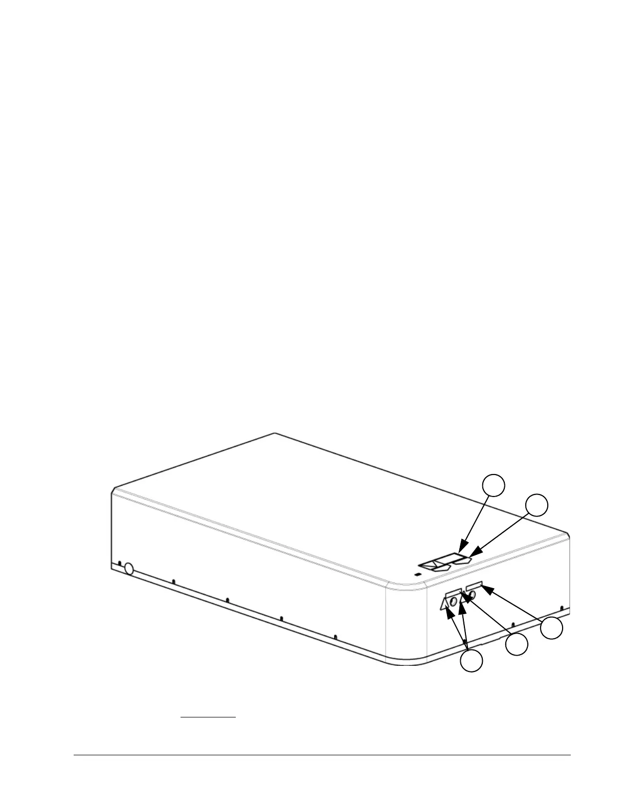
NOTE: The label numbers marked in the following figures are shown in Figure 2-11.
Figure 2-8 CE/CDRH radiation control drawing, laser head, front/top view
2. 0.39 µW for continuous-wave operation where output is limited to the 400 to 1400 nm range.
 Loading...