6-14 Operation
Operating the System Using the GUI Control Software
The Upper Section
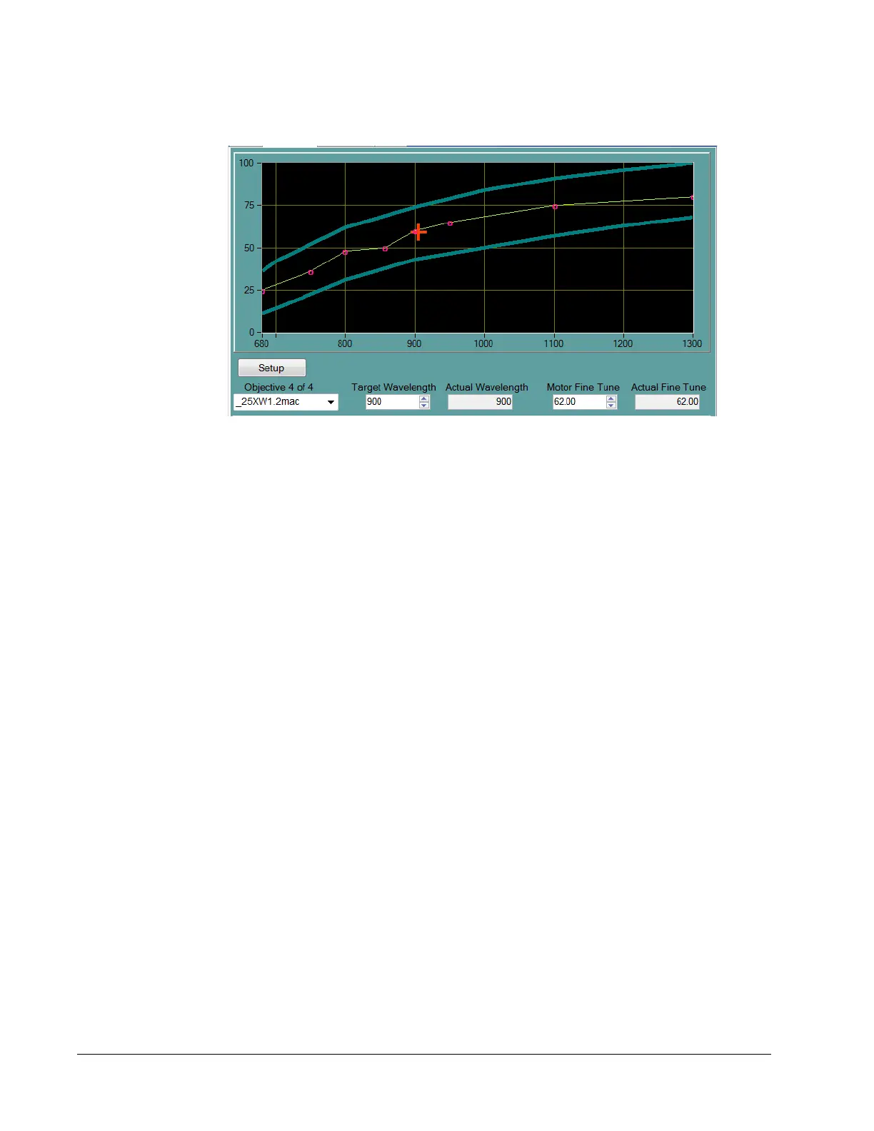
Figure 6-9 Upper section of the Objectives tab
X-Y Plot—Shows the DeepSee motor position vs. the InSight X3 wavelength. The
center green line indicates the DeepSee motor values for any given wavelength. The red
circles on the green curve are the actual user calibrated points. The green line is a best
fit interpretation. The upper and the lower curves (blue) represent the upper and lower
value limits for the motor position for any given wavelength.
Setup button—When pressed for more than 6 seconds, it opens the lower panel
(
Figure 6-10), which is used to create, save, and delete objective tables and to create,
save, and delete points that define objective tables.
Objective field—Provides a drop-down list of all the objective tables that have already
been created, plus the read-only template table, “!!template.” Use this list to select a
predefined objective table. Making a new selection causes the plot to update.
Target Wavelength field—Allows the user to tell the DeepSee controller to move to the
new InSight
X3 wavelength.
Actual Wavelength monitor—Shows the current InSight X3 wavelength.
Motor Fine Tune field—Allows the user to tell the DeepSee controller to move the
motor to a new position in percent of total possible motor motion. However, for any
given wavelength, the motor position is bounded to less than 0 to 100% by the soft limits
of travel. The red cross hair indicates the new position for the motor.
Actual Fine Tune monitor—Shows the current motor position in percent.
Lower Section
Figure 6-10 shows the default lower section that serves as a starting point for creating
or deleting an objective or data point. It also allows the operator to transfer objective
files from InSight
X3 to the control computer and vice versa. Figure 6-11 shows the
lower section after the New Objective button has been pushed.
 Loading...