Connector Interface Descriptions
Controls, Indicators, and Connections 3-8
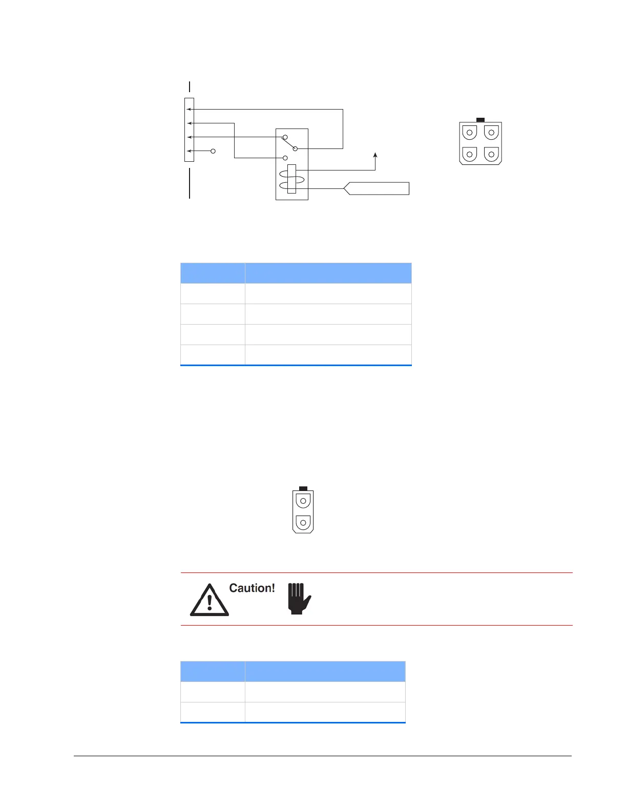
Figure 3-8 Laser head emission connector and circuit
Safety Interlock Connector
The connector shown in Figure 3-9 is part of a system interlock system. It is intended
for use by the operator. All interlocks, including this one, must be closed (shorted)
before the laser can be turned on. Opening this interlock turns off the diode laser
immediately.
Figure 3-9 Laser head interlock connector
Table 3-2 Emission connector pin descriptions
Pin # Description
1 Wiper
2 Normally open
3 Normally closed
4 Not used
EMISSION
When emission is present,
this signal is pulled low.
+ 24 V
1 Common
2 N.O.
3 N.C.
4
43
21
As viewed on the
laser head panel.
If a normally closed switch is not attached to this
connector, the provided shorting plug must be attached
or the laser does not turn on.
Table 3-3 Interlock connector pin descriptions
Pin # Description
1 System interlock
2 System interlock return
As viewed on the
laser head panel.
2
1

 Loading...