Operating the System Using the GUI Control Software
Operation 6-13
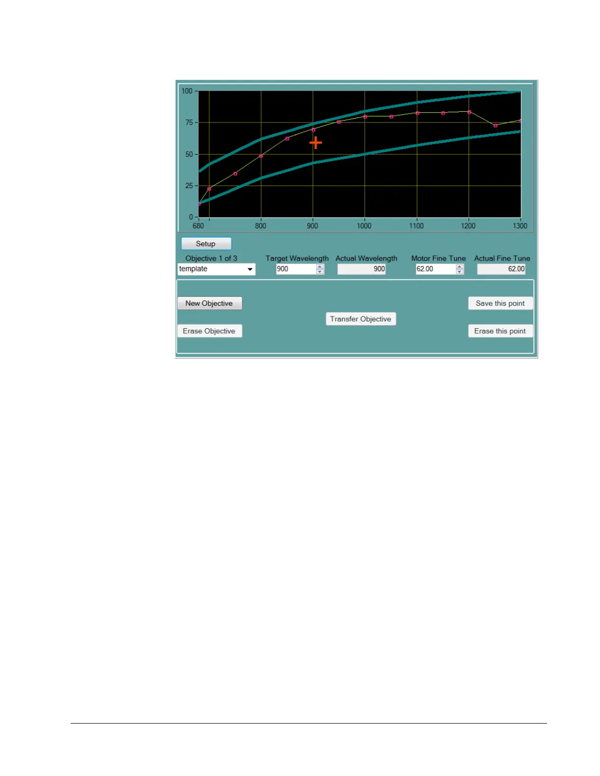
Figure 6-8 Objectives tab display
The Objectives tab display has two sections.
The upper section (Figure 6-9) includes:
An X-Y plot of the interpolated DeepSee motor position vs. wavelength coordinate
points
The basic, frequently used functions and indicators for a selected objective
Mouse selectable and numerical entry controls for setting the InSight X3
wavelength and the DeepSee motor position
To open the lower section (Figure 6-10), press and hold the Setup button for several
seconds. The lower section provides tools to:
Calibrate the table entry
Add or delete points for each objective table
Add or delete objective tables
Refer to “Changing Wavelength Motor Position” for information on how to change
motor position for a particular wavelength, and to “Calibration Points” for information
on creating calibration points.
 Loading...