Connector Interface Descriptions
Controls, Indicators, and Connections 3-7
AC Input power connector — Provides connection for primary AC input power. Power
supply inlet connector is IEC C20-style (Schurter #4798.9000). Use a cord consistent
with the current and voltage specifications printed on the rear of the unit. Provide at least
6 inches of clearance (for air flow).
Air exhaust — Allows heated air to be expelled from the power supply. This vent must
be unobstructed and clean during use.
Connector Interface Descriptions
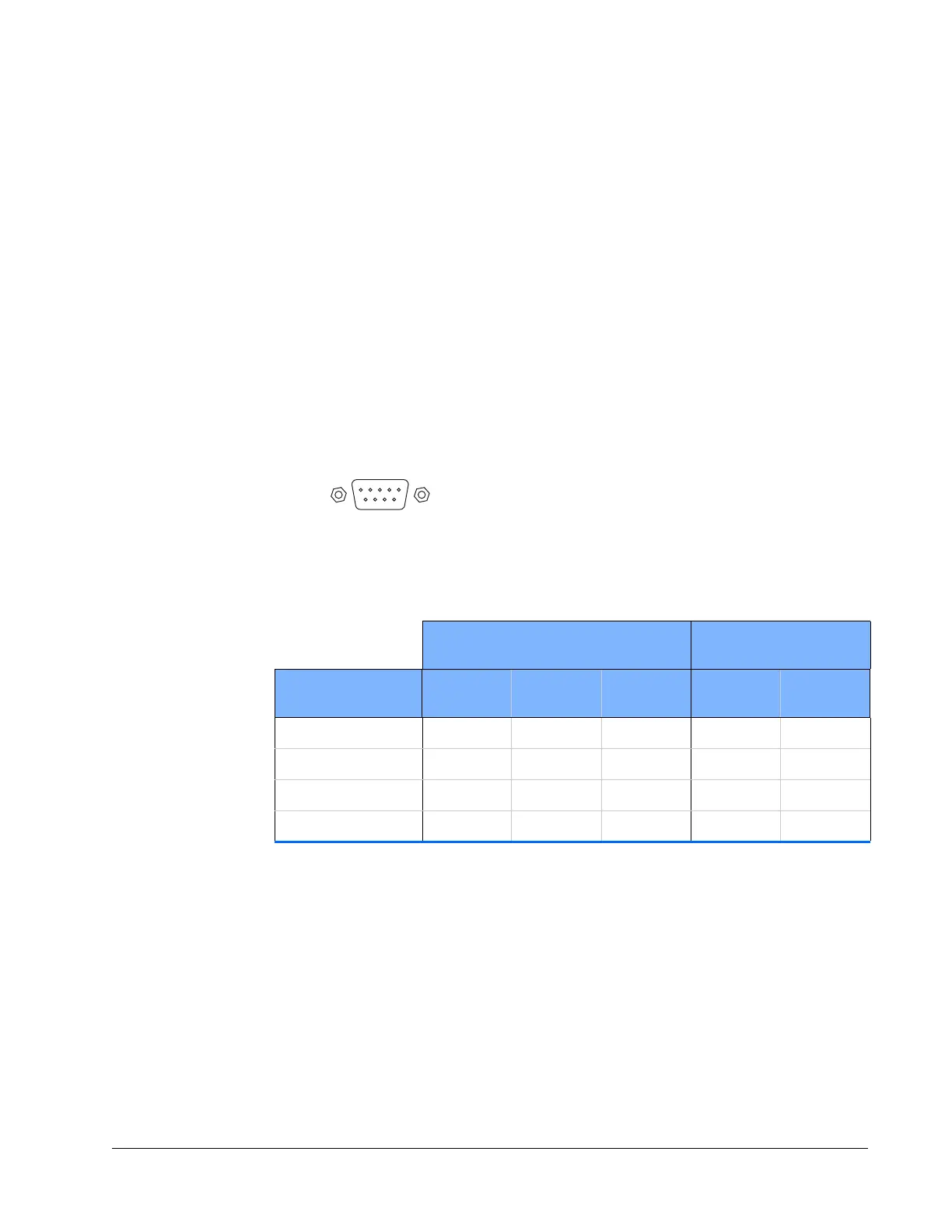
RS-232 Port Connector
The InSight X3 system uses four of the nine RS-232 pins: one pin each for the transmit
and receive signals, and two pins for ground.
Table 3-1 describes pin usage.
Figure 3-7 9-pin RS-232 port
Emission Connector
This connection can be used to turn an external emission light on and off. No power is
provided by this connector. Instead, the connector is attached to a single-pole,
double-throw relay whose contact pins 1 and 2 close when emission occurs or is
imminent. This circuit is rated for 120
Vac at 1 A.
The mating connector is a Molex 43025-0400 using pins 43030-0003.
Table 3-1 RS-232 port connections
Computer or Terminal InSight X3
Laser Head
RS-232-C Signal
Name
Signal Pin No.
(25 pin)
Pin No.
(9-Pin)
Pin No. Signal
Transmit data TXD233RXD
Receive data RXD322TXD
Signal ground 755
Protective ground 1 SHELL SHELL
 Loading...