IPS-300 Power Supply
Controls, Indicators, and Connections 3-5
Front Panel
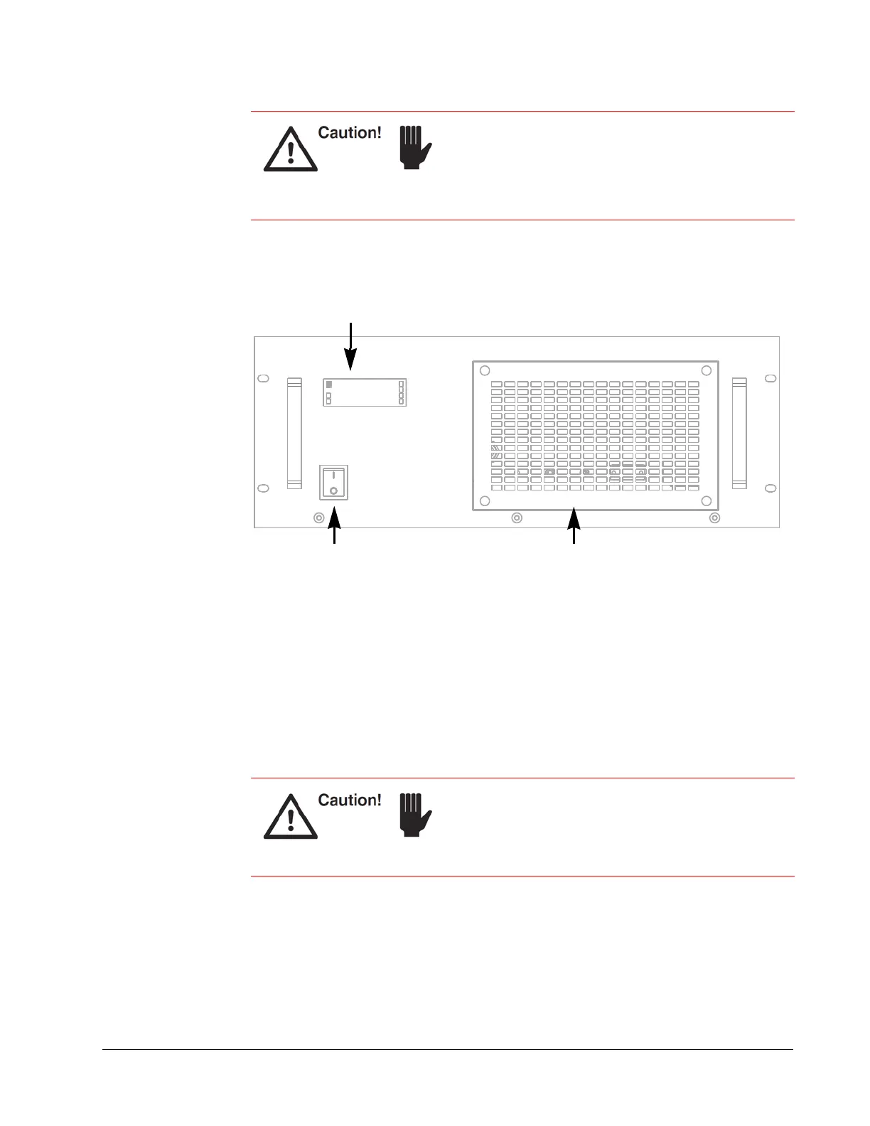
Figure 3-5 Power supply front panel
LCD display — Displays the current wavelength as well as the status of the power
supply during normal operation and any status or fault codes that are generated by the
power supply. During start up, this panel displays the status of the self-diagnostics
program. If problems ever occur, monitor this panel to see where they occur. All
warnings, including errors generated by the system and indications related to proper
system operation, are displayed on the control computer as well.
AC power on/off switch — Provides AC power to the power supply. The switch glows
amber when providing AC power to the system.
Air intake panel — Allows cooling air to be drawn into the power supply. The heated
exhaust air is then vented from the rear panel (see
Chapter 7, “Maintenance and
Diagnostics”).
Provide at least 6 inches of room on the front and back
of the power supply to allow cool air to enter the front
and for the heated exhaust air to exit the rear panel.
Inadequate cooling causes the system to overheat.
Damage to components caused by insufficient cooling
is not covered by your warranty.
Never turn off the power switch before exiting the laser
GUI or using RS232/USB commands to shutdown the
laser.
Refer to Chapter 6, “Operation,” for a detailed
explanation of how to shut down the laser safely.
LCD display
On/off AC power switch Air intake panel