Operating the System Using the GUI Control Software
Operation 6-17
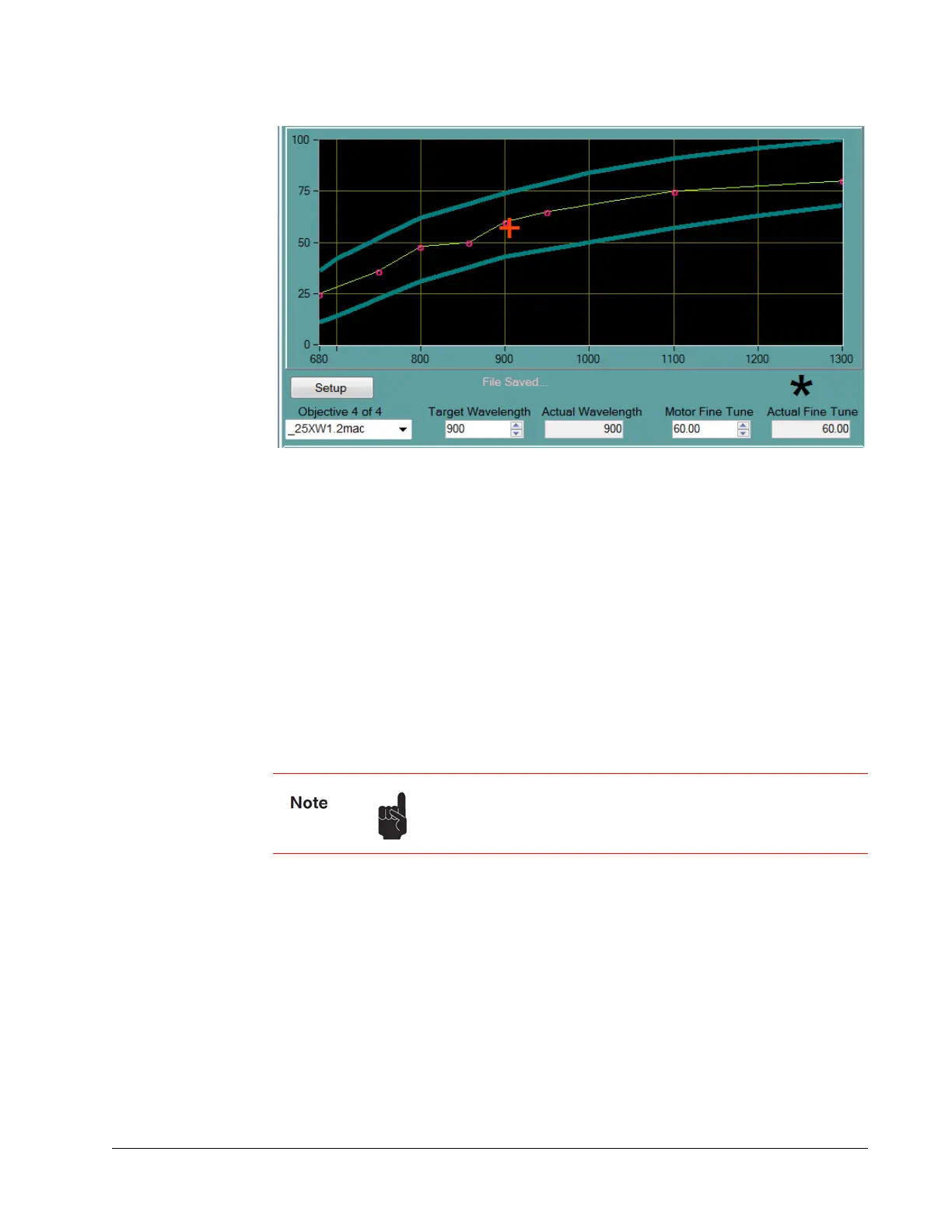
Figure 6-12 Upper section of Objectives tab
Change the motor position by entering a percentage value (percentage of full motor
travel) in the Motor
Fine Tune field. The red cross-hair symbol moves along the
vertical axis. Both the wavelength and the motor position entry fields have value range
checks.
The blue lines show the interpolated soft limits. The motor position in the plot is
clamped to within these limits except when the motor is homed.
Calibration Points
Two indicators for a calibrated point exist in the table when:
There is a black asterisk above the Actual Fine Tune box (Figure 6-12).
There is a little open circle on the objective curve.
Diagnostics Tab
The Diagnostics tab (Figure 6-13) provides detailed operating information about the
laser and allows the user to select specialized operating modes. Included is a control to
initiate an optimization routine. The Run/Align switch allows the operator to select
standard operation mode (Run) or to alignment mode (Align) where output power is
reduced to allow the operator to align the laser beam to external optics.
Also included is the Imaging Control button, which allows the user to make extremely
high-resolution images by temporarily shutting off the automatic laser controls that
actively adjust the laser.
If many adjacent points exist in the table, the curve appears
thicker. If a point does not exist, the Erase this point button is
disabled.
 Loading...