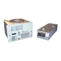
Laser Head
Controls, Indicators, and Connections 3-3
Power Control connector — Provides connection for the power control cable that
connects to the matching connector on the power supply. As the name implies, it
delivers control signals from the laser head to the power supply to control the power to
the laser head.
RS-232 connector (9-pin, D-sub) — Operates the laser with user-developed software in
lieu of the supplied GUI software. To use this port, connect the host computer to this
interface using a standard M/F serial cable. Refer to
“Command/Query/Response
Format” on page A-1 for information on sending commands to the InSight X3 system.
Refer to “RS-232 Port Connector” on page 3-7 for pin connections.
Use either the RS-232 or the USB port for communications, but not both.
USB connector — Operates the laser using the supplied GUI software or
user-developed software in lieu of the GUI software. Prior to using this port, the USB
driver provided on a USB flash drive (located in the accessory kit) must be installed. If
the optional notebook computer is used, the GUI software and USB driver are already
installed.
To use this port with user-developed software, refer to “Command/Query/Response
Format” on page A-1 for information on sending commands to the InSight X3 system.
Use either the RS-232 or the USB port for communications, but not both.
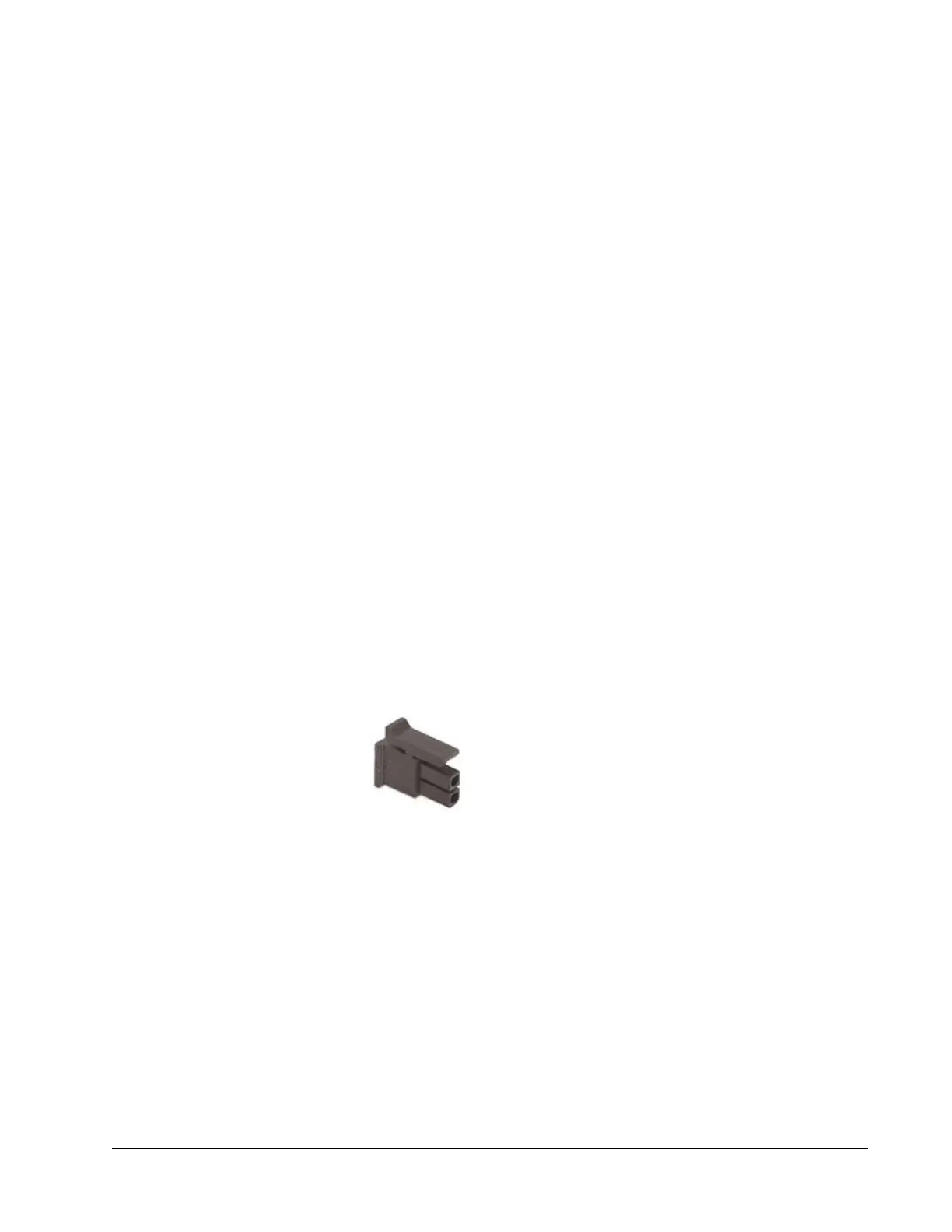
interlock connector (2-pin) — Provides attachment for a safety switch that can be used
to turn off the system in an emergency. These two contacts must be shorted together
before the laser can turn on. A defeating jumper plug (
Figure 3-2) is installed at the
factory to permit operation without a safety switch. Replace this plug with a similar,
non-shorting plug that is wired to auxiliary safety equipment (such as a door switch) to
shut off the laser when actuated (the switch opens). Such a switch must be designed for
24
volt, 100 ma signal.
The mating connector is a Molex 43025-0200 using pins 43030-0003.
Figure 3-2 Mating interlock connector
Emission connector (4-pin) — Provides access to relay contacts that close when
emission is present. This can be connected to a supply voltage and lamp to provide
remote indication of laser emission. When the laser is off (i.e., when there is no
emission), there is closure between pins 1 and 3 (refer to
“Emission Connector”). When
the laser is on, there is closure between pins 1 and 2. Pin 4 is not used. No power is
supplied by these terminals. This circuit is rated for 120
Vac at 1 A.
The mating connector is a Molex 43025-0400 using pins 43030-0003.
 Loading...