3-1
CHAPTER 3: Controls, Indicators, and
Connections
Introduction
This chapter describes the user controls, indicators and connections of the InSight
®
X3
™
laser system. It is divided into three sections: the InSight
X3 laser head, the IPS-300
power supply, and the connector interface descriptions. (
Chapter 6, “Operation,”
explains how to use the included InSight X3 GUI control software.) Information on the
chiller can be found in the chiller user’s manual that is shipped with that unit.
Each section below describes the various controls from top to bottom, left to right.
Laser Head
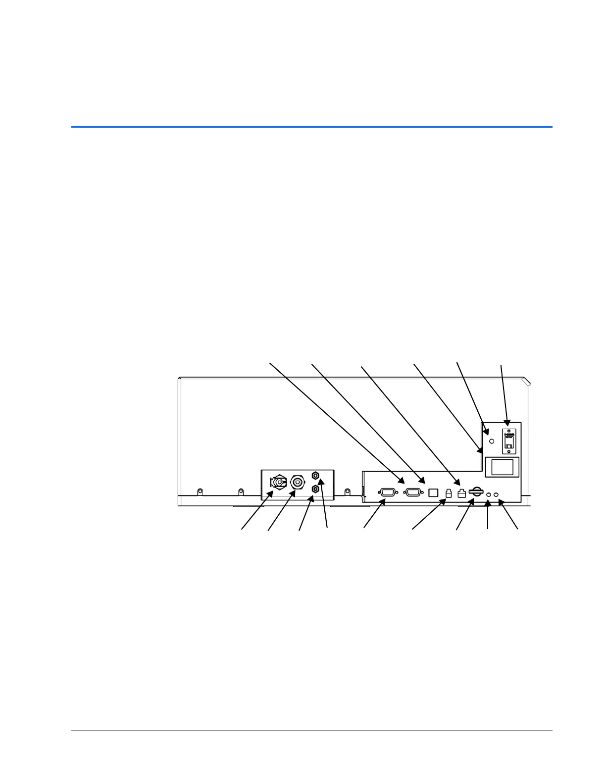
Figure 3-1 Laser head rear panel controls, indicators, and connectors
Controls
Laser enable interlock keyswitch — Provides interlock safety to prevent unauthorized
personnel from using the InSight
X3 laser system when the key is turned to the off
(horizontal) position and the key is removed. Turning the key to the enable (vertical)
position allows the diode laser to be energized if the AC power switch on the power
supply is also on and the ON command is given.
Fault
LED
Key
switch
Com
LED
Out In
Coolant
Power
control
Safety
interlock
DC power
input
Emission
Serial interface
RS-232 USB
Service
control
Out In
Air purge
Sync out