6.3.2.2 Height adjustment for various types of support wheels
► In order to be able to loosen the height adjustment fasteners on
the support wheels: Lift the hoeing implement to the pressureless
zone using the tractor’s three-point linkage.
The type of height adjustment diers for the various types of support
wheels.
CAUTION
Risk of being crushed at moving mechanical compo‐
nents
Components with a high dead weight can move down‐
wards independently.
– NEVER reach between components that can move
independently under their own dead weight.
– When moving the components manually: Wear pro‐
tective gloves.
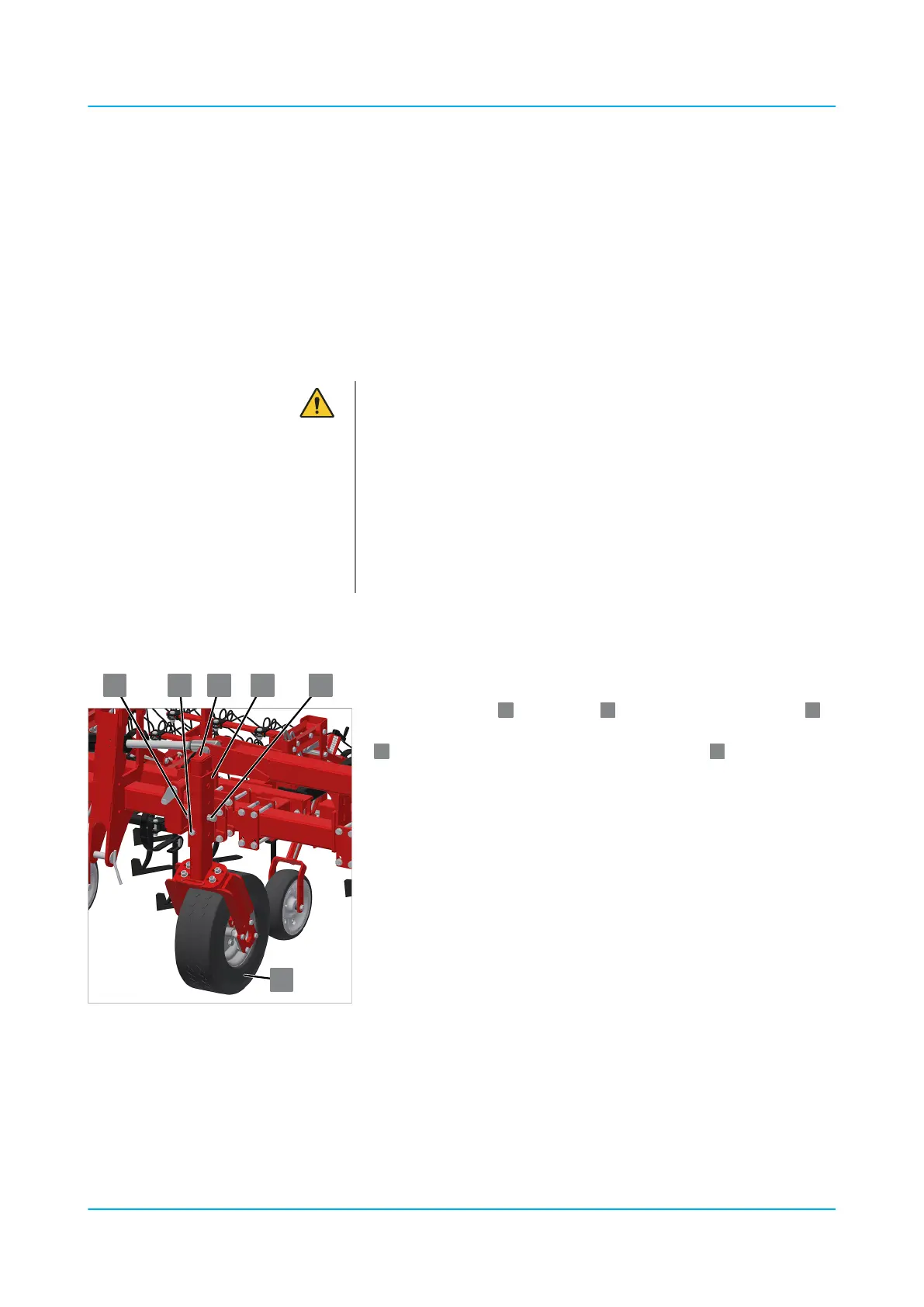
Rear mounting: Basic-Elements, Combi-Elements, TRS-Elements
The support wheel
has an outer
and an inner mounting tube
with rows of holes. The desired height is adjusted by inserting the pin
through the holes and securing it with a linch pin
.
The rows of holes in the inner and outer tube are arranged asynchro‐
nously and enable height adjustment from bottom to top in the fol‐
lowing increments: 10 mm, 10 mm, 20 mm, 20 mm, 10 mm, 20 mm,
20 mm, 30 mm, 20 mm.
1. Undo the hexagon bolt.
2. Dismantle the pin.
3. Lift the implement with the three-point linkage of the tractor to the
desired height.
4. When the openings of the inner and outer mounting tube are
exactly above each other: Insert the pin.
5. Secure the pin with a linch pin.
6. Lower the hoeing implement.
Prepare height adjustment
Support wheels adjusted via a pin
Operation
en-GB | Item no. 17513597 | BA 02/05-2022 68