Instruction Manual
for
AS380 Series Elevator Integrated Drive Controller
109
JP9
1 Output GY5, standby
2 Output JP9.1 common port
JP3
1 Input GX7, standby
2 Input GX8, standby
3 Input GX9, standby
4 Input power supply need to connect the
power supply of switch +24V
JP4
1 Input GX10, door opening holding button
input
Default NO
2 Input GX11, NS-SW Default NO
3 JP4.1-JP4.2 Input common port,0V
JP5
1 Input GX12, standby
2 Input power supply , need to connect
switch power supply+24V
Note:
car control board is linked to the power supply and communication bus
The power supply and communication of car control board is lined in with JP1, in which
JP1.01 and JP1.02 is TXV+ and TXV-. JP1.03 and JP1.04 is TXA+ and TXA -,
The input power supply of TXV+,TXV- is DC24V. TXA+ and TXA- is communication
line. The communication line must be 4-wire twisted pairs.
car control board input signal connection
Car control board mainly collect car switch-generated data signal, and transmit these signal
status to main controller through CAN bus. These switch-generated data signal such as door
open/close input, attendant, by-pass, etc.
car control board output signal connection
Car control board control the transistor output through the signal transmitted from CAN bus.
The transistor output control the output of door-opening/closing button lamp.
the connection between car control board and instruction controller
The connection line between instruction extension control board and car control board is
preinstalled in the car. And the pin plug into the JP2 groove
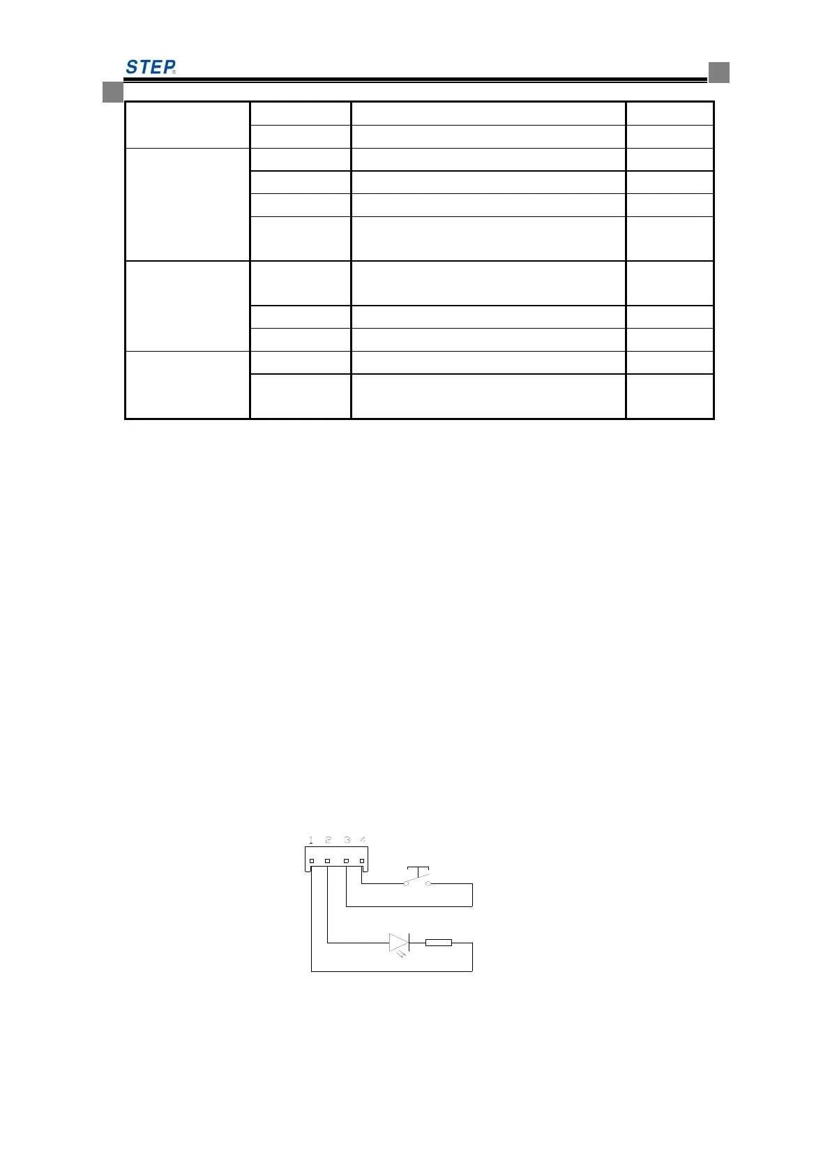
door opening/closing button and indicator lamp connection instruction.
1 and 2 pin connecting respectively to “-“and “+” terminal of power supply of door indictor
lamp. 3 and 4 pin connecting to the button terminal of door opening and closing
Fig 6.7 door opening/closing button and instruction lamp connection diagram
6.4 instruction control board SM-03
 Loading...