Instruction Manual
for
AS380 Series Elevator Integrated Drive Controller
52
controller overheat or damage.
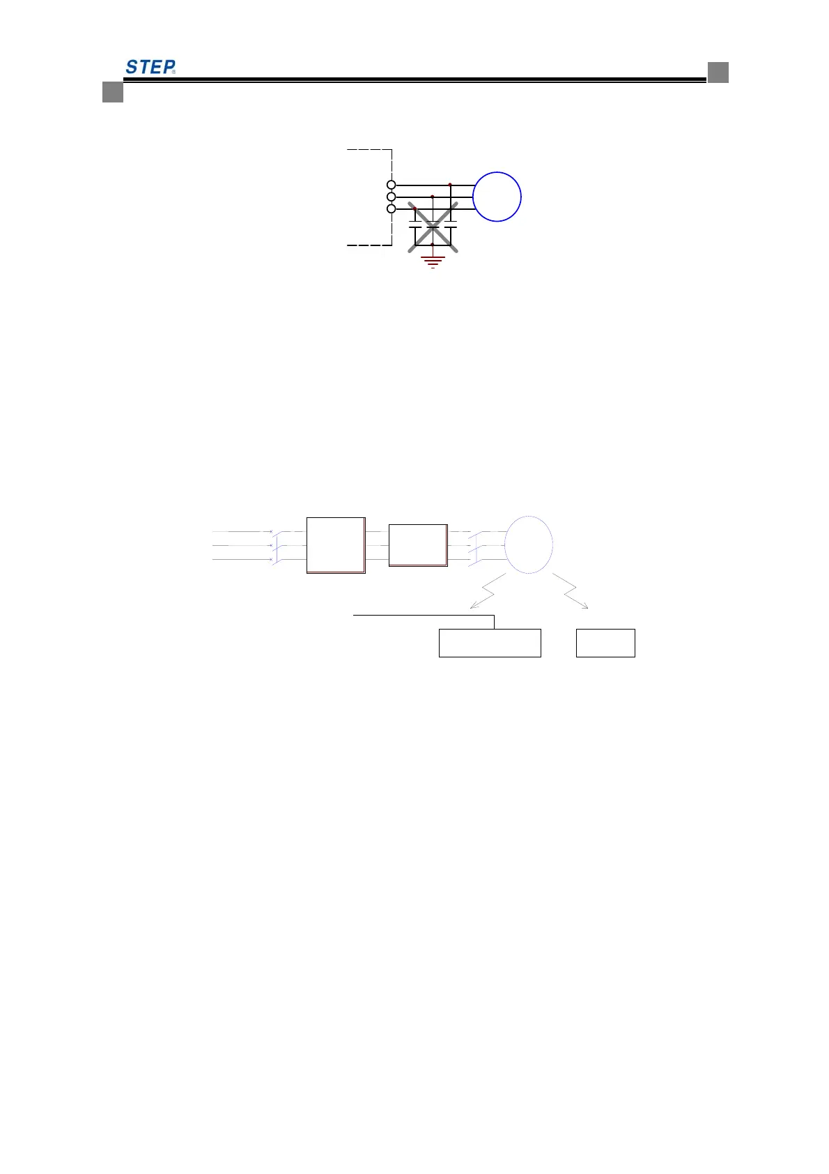
No connection of capacitor at the output side of integrated drive controller see fig 4.13
V/T2
U/T1
M
W/T3
The schematic diagram of no connection of capacitor at the output side of integrated drive
controller
4.5 anti-interference measures.
4.5.1 The specialized noise filter connected at the output side.
In order to suppress the noise created at the output side of integrated drive controller,
specialized noise filter can be connected at the output side of integrated drive controller. please see
fig 4.14 for the wiring of noise filter at the output side of integrated drive controller.
Fig .4.14 the wiring at the output side of integrated drive controller
4.5.2 Main circuit wiring arrangement
In order to suppress the radiated interference created at the output side of integrated drive
controller and improve the anti-interference performance, the wire of main circuit and that of
control circuit should be separated. The wire of main circuit should go through the grounding
metal tube and should be 10cm away from the signal wire. The wiring arrangement of main circuit
is as below fig 4.15
Noise
filter
Control device
Radio
Radiation interference
power
supply
M
AIO drive
controller
 Loading...