Instruction Manual
for
AS380 Series Elevator Integrated Drive Controller
136
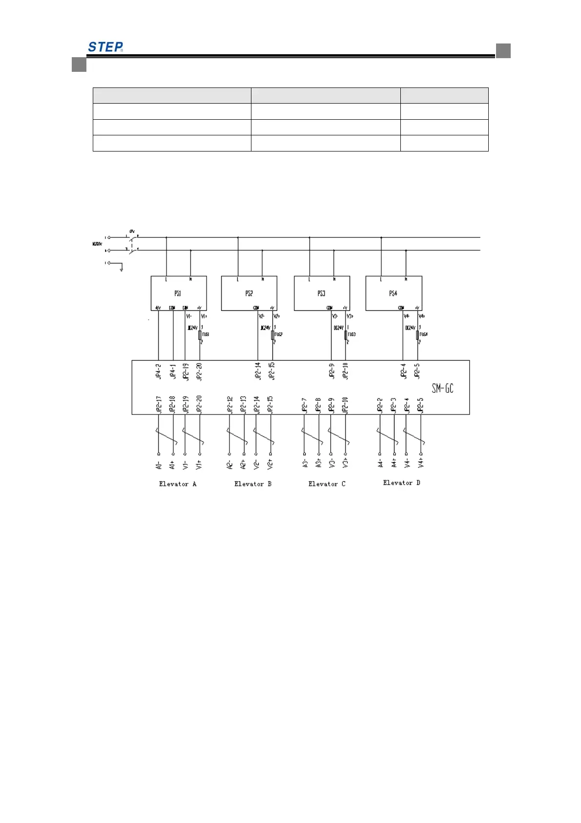
6.6.8 Connection Diagram of Group Control System
This figure shows the joining method for four elevators’ group control
PS1、PS2、PS3、PS4 are switch power supply, PS1 has +5V(3A)and +24V(1.8A)output,
PS2、PS8 and PS4 have only +24V(1.8A) output. FU1、FU2、FU3、FU4 are over-current protection
devices,SM-GC is group control board.
6.6.9 Setting of group control running
6.6.9.1 Setting of group control
1.Connection
After the mono-elevator’s commissioning, do the group control system’s commissioning. Joining
the group-control cabinet, connect Elevator No.1 which has been appointed in the agreement to
the output port of JP2.17~JP2.20 of group controller, connect Elevator No.2 listed in the
agreement to the output port of JP2.13~JP2.16 and so on. If the total floors, stop floors or serial
number of elevators in the group-control system are changed which are discordant with the
agreement in the site, please inform us. Perhaps unpredictable mistake will happen, and the group
control will fail.
2.Setting of wire jumpers
SM-GC(P1) Laptop(RS232)
Note
2 3 RXD
3 2 TXD
5 5 SGND
 Loading...