Instruction Manual
for
AS380 Series Elevator Integrated Drive Controller
124
JP4
Down-call terminals, of which Pin 1- and Pin 2+ for button indicator, Pin 3 and Pin 4
for button input.
CH2510-4
JP5
Pin 1 and Pin 2 is the elevator-lock indicator output, Pin 3 and 4 are Normal open
contact input of elevator-lock
CH2510-4
JP6
standby CH2510-4
S1
Set the address codes of the display Board with the jumper on, after that the jumper
MUST BE REMOVED.
S2
Bridge S2.1 and S2.2 to use JP2 as the button of three-wire system, otherwise , used as
utton for four wire s
stem.
S3
Bridge S3.1 and S3.2 to use JP3 as the button of three-wire system, otherwise, used as
utton for four wire s
ste
SW1
Resistor jumper of serial communication terminal, meanwhile shorting means the
connection of built-in 120Ω resistor.
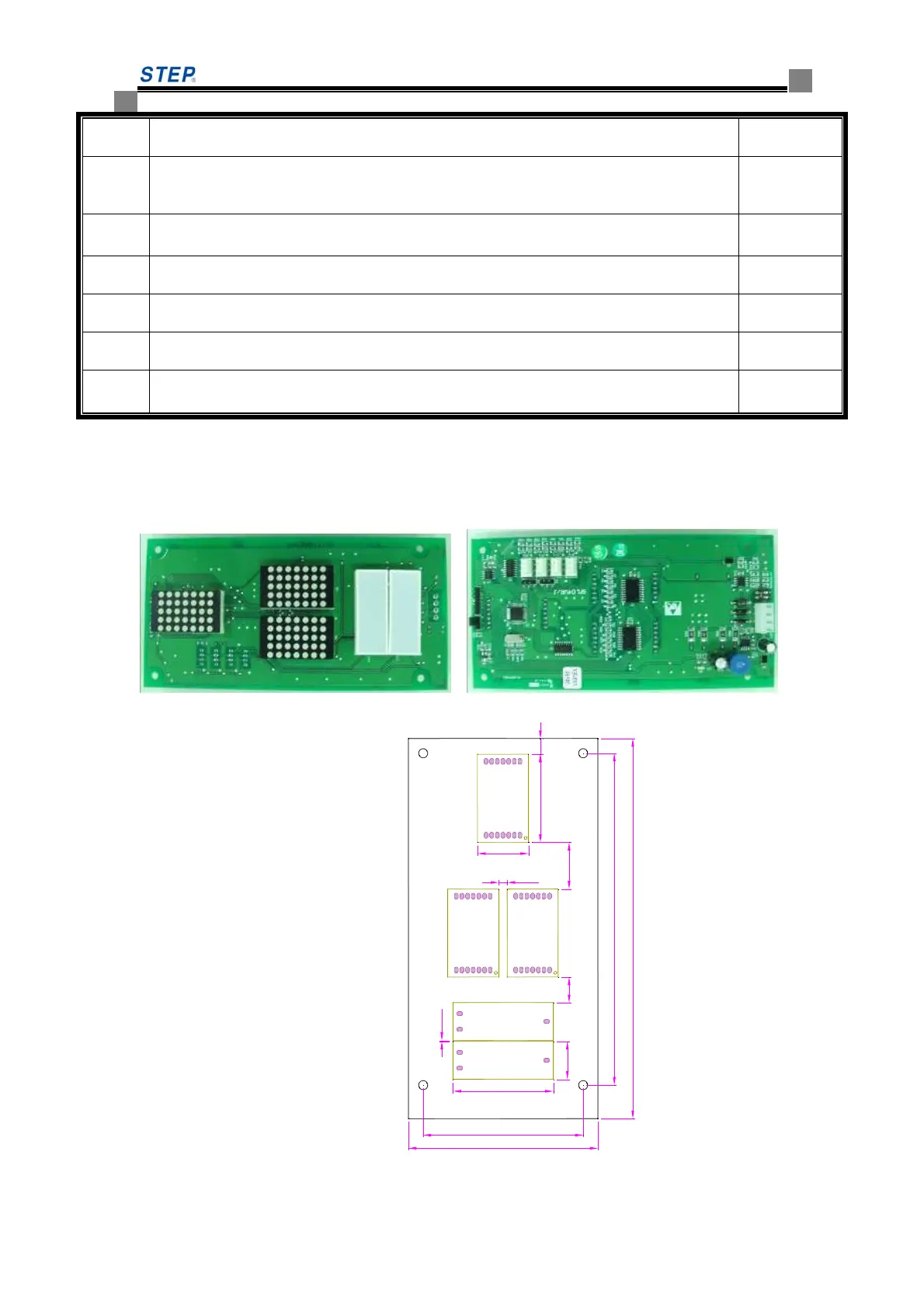
6.5.8 Call & LED display SM-04-VRJ
SM-04-VRJ outside view and installation dimension
Fig 6.29 SM-04-VRJ outside view
148.4
71.8
170
85
39.4
22.8
45
17
20.911.5
0.3
3.9
7
Fig 6.30 SM-04-VRJ installation dimension
 Loading...